Aircraft Procedure - Introduction
Pilots
are highly trained professionals who fly airplanes and helicopters to carry out
a wide variety of tasks.
Except
on small aircraft, two pilots usually make up the cockpit crew. Generally, the
most experienced pilot, the captain,
is in command and supervises all other crew members. The pilot and copilot share
flying and other duties, such as communicating with Air Traffic Controllers and
monitoring the instruments. Some large aircraft have a third pilot—the flight engineer—who assists the other pilots by monitoring and
operating many of the instruments and systems, making minor in flight repairs,
and watching for other aircraft. (but nowadays this duty is performed by pair of
computers) New technology can perform many flight tasks, however, and
virtually all new aircraft now fly with only two pilots, who rely more heavily
on computerized controls. As older, less technologically sophisticated aircraft
continue to be retired from airline fleets, the number of flight engineer jobs
will decrease.
Before
departure, pilots plan their flights carefully. They thoroughly check their
aircraft to make sure that the engines, controls, instruments, and other systems
are functioning properly. They also make sure that baggage or cargo has been
loaded correctly. They confer with flight Dispatchers and aviation weather
forecasters to find out about weather conditions en route and at their
destination. Based on this information, they choose a route, altitude, and speed
that will provide the fastest, safest, and smoothest flight. When flying under
instrument flight rules—procedures governing the operation of the aircraft
when there is poor visibility—the pilot in command, or the airline dispatcher,
normally files an instrument flight plan with air traffic control so that the
flight can be coordinated with other air traffic.
Takeoff
and landing are the most difficult parts of the flight, and require close
coordination between the pilot and first officer. For example, as the plane
accelerates for takeoff, the pilot concentrates on the runway while the first
officer scans the instrument panel. To calculate the speed they must attain to
become airborne, pilots consider the altitude of the airport, outside
temperature, weight of the plane, and speed and direction of the wind. The
moment the plane reaches takeoff speed, the first officer informs the pilot, who
then pulls back on the controls to raise the nose of the plane.
Unless
the weather is bad, the actual flight is relatively easy. Airplane pilots, with
the assistance of autopilot and the flight management computer, steer the plane
along their planned route and are monitored by the air traffic control stations
they pass along the way. They regularly scan the instrument panel to check their
fuel supply, the condition of their engines, and the air-conditioning,
hydraulic, and other systems. Pilots may request a change in altitude or route
if circumstances dictate. For example, if the ride is rougher than expected,
they may ask air traffic control if pilots flying at other altitudes have
reported better conditions. If so, they may request an altitude change. This
procedure also may be used to find a stronger tailwind or a weaker headwind to
save fuel and increase speed.
Pilots
must rely completely on their instruments when visibility is poor. On the basis
of altimeter readings, they know how high above ground they are and whether they
can fly safely over mountains and other obstacles. Special navigation radios
give pilots precise information that, with the help of special maps, tells them
their exact position. Other very sophisticated equipment provides directions to
a point just above the end of a runway and enables pilots to land completely
“blind.” Here the air traffic engineers play major role to keep the ground equipment
to their absolute specification for "blind" landing. Once on the
ground, pilots must complete records on their flight for their organization and
the FAA. report.
Although flying does not involve much physical effort, the mental stress of being responsible for a safe flight, no matter what the weather, can be tiring. Pilots must be alert and quick to react if something goes wrong, particularly during takeoff and landing.
Simple lesson plan
to fly
Flight
Plans
Pilots wishing to fly under IFR rules must first file a
flight plan with Air Traffic Control, before departure. Calling the
Aeronautical Information Office can do this. The flight plan contains the
aircraft identification, or callsign, the type of aircraft, planned speed
(true airspeed, or speed across the ground without wind), requested route
of flight (from VORTAC to VORTAC), planned cruising altitude, and sometimes
other information such as color of aircraft, and number of people on board. We
will discuss all these later and for the time being have these in mind.
This flight plan information goes into the Air Traffic
Controllers and they prepare a strip of paper called a flight progress
strip. After that, controllers can review the proposed route of flight and
make changes as necessary to conform to local procedures and routings.
When the aircraft is ready to depart, the pilot calls either
the control tower and requests clearance. The controller checks the
flight strip, and clarifies the routing and any changes to the routing with the
pilot, so both pilot and Air Traffic Control know the exact route the pilot will
fly.
The controller also tells the pilot his flight plan code
number, and the pilot sets an instrument on his aircraft called a transponder
to transmit this code. This beacon code transmission is picked up by radar,
allowing the ATC computer to know exactly which aircraft it is, and which flight
plan it corresponds to.
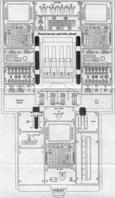
Getting started
Imagine you
enter the cockpit of a parked A340 - everything is ready except that all systems
are shut down. APU (Auxiliary power unit) and engines are also switched off.
Now
both batteries are switched on at the Overhead ELEC panel.
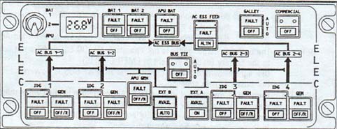
Overhead
ELEC (electrical) panel
The next
thing to do is to check the APU fire warning. To do this, the TEST button on the
APU fire panel is depressed and released when the fire light illuminates.
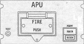
APU
fire warning
Now the APU
is switched on by pushing the MASTER switch on the APU panel.
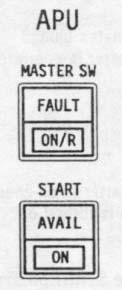
APU
panel
When
the "FLAP OPEN" message appears on the ECAM (Electrical Contactor and Management Unit)
the APU start switch is depressed.
When the
AVAIL light illuminates, the APU bleed push button on the AIR panel is pushed to
supply the air conditioning and other systems with air.
Check
the all panels for white lights out and turn the three IR switches to NAV for
the alignment process.
Refer to
the following MCDU (Multifunction
Control Display Unit) programming
procedure.
STATUS PAGE (PS)
The
DATA BASE validity must be checked at first, as well as the navaids and
waypoints.
FLIGHT PLAN
Should be completed thoroughly. It
includes data like: Take off runway, SID with ALT/SPD data, expected take off
time, course, waypoints and the expected step climbs descents
SEC FLIGHT PLAN
Must be filled in when ever a
specific condition is likely to happen such as take off runway change,
alternative SID etc.
RAD NAV (Radio and Navigation)
Any required Navaids manually entered
using ident.
INIT
Winds,
expected ZFWCg (Zero
Fuel Weight Center of Gravity / ZFW (Zero Fuel Center
of Gravity),
Fuel planning: The FMGS (Flight Management Guidance System)
calculation the minimum required fuel this value must confirmed. After that, the
DATA page is selected and the preflight data is printed out using the ACARS
(Aircraft Communications Addressing and Reporting System). The
printed sheet must be kept as it gives the required fuel for each waypoint of
the Flight Plan.
PERF (Performance)
The derated climb and descents and
speeds are typed in - this is necessary.
Flight plan checked:
MCDU: FPLN page ND (Navigation
Display) in plan mode: range as required, with CSTR selected on EIS CTLE panel.
ALT/SPD checked, Distance to successive waypoint is provided. The overall
distance of the route is indicated in the 6th line of the MCDU
Now the
before Start Checklist (written on the table) can be completed. Before starting
the engines, turn the beacon light on and seat belts to on.
ATC communication
Now check
your departure time and you are ready for startup. Before that, contact the
control tower (Aerodrome) for clearance for startup and pushback the aircraft to
taxiway.
Engine Start up
The normal
engine start procedure is the AUTO START procedure. In this case the FADEC
prevents start malfunctions like hot start, stall etc. It recognizes all of
these and takes appropriate actions for instance reducing fuel flow, cranking
the engine, attempting new starts or cutting fuel flow. The air from the APU (APU
bleed) allows to start 2 engines simultaneously.
The engine
start up sequence is simple: 1 and 2 are started firstly to pressurize the green
and blue system which supply the parking brakes and hydraulic actuators. An
actuator is a little box that converts the electrical inputs to real rudder
movements. The Boeing B707 for instance doesn't have this system. Engine 1 and 2
first, followed by 3 and 4. Check thrust levers idle.
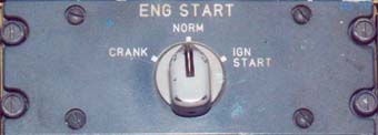
Engine Start
Then set IGN/START
to START - now an eye must be kept on the ECAM to check if APU bleed is stable.
ENG1 Master switch is set to ON followed by ENG 2 when N2 of Engine 1 has
reached 10%. Now monitor and check in the right order: Start valve open (now
high pressure bleed air (minimum 30psi) air is blown into the engine), N2 IGN A
or B, Fuel flow, EGT OIL PRESS ignition rising. FADEC (Full Authority Digital
Engine Control) closes the start valve when N2 reaches 50%, now monitor EGT and
ENG Vibration and the engine AVAIL which illuminates when the start sequence is
over. Now the same is repeated for ENG 3 and 4.
When all
engines are running stable set the IGN / START switch back to NORM which
automatically switches the Packs back ON. If, for any reasons, there is an
abnormal start DO NOT interrupt the FADEC protective and just follow the ECAM
instructions if they appear.
Another
procedure to start the engines is the MANUAL START, which is only used in
exceptional cases, like high altitude airports or subsequent low APU bleed
pressure or to CRANK the engine dry prior opening the fuel flow.
Overhead Panel
Taxi
When all
engines are running check both left and right side for any obstacles let the
tore bar to pull the aircraft on to the correct path from the apron. Again,
contact the tower and get the clearance to enter the taxiwayan most of the time
you will be asked to enter the taxiway either to runway 22 or 04 and hold short
of runway. Now, smoothly move the thrust levers forward - only a few centimeters
as otherwise you would blow everything away that is standing behind you and
therefore you do not exceed N1 40% during taxi.
The APU
bleed should be turned off to avoid ingestion of exhaust gases by the
passengers.
On straight
taxiway and shallow turns the pedals are used to steer the aircraft but the hand
is kept on the steering tiller is used in sharp turns. Be careful with that - it
is very sensitive so move this wheel very slowly. Also, when on the ground do
not start turns too early. Remember that the nose gear on the A340 is far back
(4 meters), this means that the cockpit has to be over the grass in an
intersection. If you turn too early the main gear can end up in the grass so
make sure to over steer significantly.
Slowly move
the thrust lever 1 (left one) slightly forward to make a right turn and use the
right lever for number 4 engine slightly forward to make a left turn. It is not
recommended to use differential braking to avoid gear stress. The speed
shouldn't exceed 10 knots in turns also if brake temperature exceeds 150°
degrees the brake fans (not installed in all aircraft) must be switched on.
Remember to taxi slowly at about 10-12 knots. You usually do not use thrust
reverser during taxi and it is used on old 737-200s or MD80s but not on the
newer aircrafts.
Extend the
flaps to 1 + F the lever is located on the center panel and you simple pull the
handle up and move it down one step. Make sure the stabilizer trim is in the
green range and the rudder trim at zero.
Take
off
Here you
have come most critical point of your adventure. Contact the tower again and
request for take off. You will be cleared to enter the runway and takeoff.
When turning
onto the runway, switch on the strobes and landing lights and align the aircraft
on the center line and select Auto Brake MAX on the main instrument panel (below
the gear indicator)In case of an engine failure the aircraft stops automatically
when the thrust levers are moved to IDLE. Then push the CONFIG test on the ECAM
so as to insure that the ECAM take off check list items are all green.
If
everything is set the thrust levers are moved slowly to 50% N1 and when all
engines are running stable at 50% move the levers the stops (TOGA). A yellow
arrow appears on the PFD indicating the acceleration. Now full concentration is
needed to monitor speed, engine gauge and the aircraft on the centerline.
At 90 knots, the rudder has to be used to keep the aircraft aligned with the centerline as at 100 knots the nose gear steering disconnects from the nose gear.
This is actually the most tricky part of the take off run and in case of an engine failure it is difficult to keep the aircraft aligned with the center line as the airspeed is still to low for an effective rudder and the nose gear steering is disconnected.
This
is why much attention has to be paid on the engine gauges at this stage to react
as early as possible. At 140 knots smoothly move the side stick backwards to
gain a pitch attitude of 8° to avoid tail strike and then to 12-15° (depending
on weigh). The Autopilot is available 5 seconds after take off.
CLB/CRZ/DES(Climb/
Cruise/ Descend)
When a
stable positive rate of climb is established the gear is selected up and thrust
reduced to CLB at 1500feet. The flaps are retracted at 200kts but as this only a
traffic pattern they are set to 1. In case of a traffic pattern, usually you
maintain 1500 feet above ground. You can use the autopilot for the traffic
pattern. Just press AP1 and Pull + rotate the altitude knob to 1500 and then
pull it. Now select your desired heading - simply add 180° to your current
heading to make a 180-degree turn to fly the downwind leg of the traffic pattern.
From now on, until landing, the aircraft is under observation of the Air Traffic
Control system. After departure, ATC issues altitudes, speeds, headings, and
sometimes re-routes as necessary, and assumes responsibility for separating the
aircraft from all known traffic.
Landing
Put the FLAP
lever to 2 and select 160 knots airspeed. Now put the gear lever to down and the
FLAP lever to 3. Select 140 knots speed. Before turning on final extend the
flaps to FULL and arm the spoilers and push the Autobrake switch to Medium - you
do not use Autobrake max during landing. Now the aircraft should be aligned with
the runway centerline with the localizer display indicator and have an airspeed
of 140 knots with the gear down and flaps set to FULL and a rate of descent of
700-800 feet per minute and a pitch angle of 4-5°(but the actual landing angle
should be 3°). These parameters need to be monitored constantly - never fix
your eyes on one parameter always keep all parameters in view.
The PAPI
will help you to establish the correct glide path. The PAPI (Precision Approach
Position Indicator) consists of 4 lights which can illuminate red or white. If
you see 2 red and 2 white lights than the glide path is correct - if 3 reds and
1 white is seen than slowly add power and smoothly pull the stick backwards to
reduce the ROD. But most of you will know how this works either from real life
or from the flight simulator.
When passing
500 feet a voice message is heard indicating 500ft so monitoring altitude above
ground does not have high priority.
It is very
important to keep the speed at 140 knots and if it is below 140kts then in most
cases this will result in a hard landing if the speed is to high the aircraft
will climb during the landing flare.
Switch the
Autopilot off by pressing the red side stick button twice and press one of the
red buttons twice on the thrust levers to disengage the outthrust system. A
short aural warning will be hared. Continue descent at 700 feet per minute until
reaching 30 feet. Now reduce rate of descent to half and count slowly 1, 2, 3
while retarding the thrust lever to idle when the retard call is heard. Avoid
push the stick forward if not absolutely necessary and
this will increase the rate of descent and result in a hard landing. To
make it correct always give very little side stick inputs and monitor what
happens and if descending to fast pull the stick back again but always small
inputs and monitor speed. Also remember a nice approach is almost a nice landing
so if you monitored all parameters well a soft landing is not guaranteed.
When the
forward boogie touches the ground move the thrust reverser levers upwards and
the spoilers will be extend automatically. Now the landing is not over at all
and the nose gear has to be landed as well and if you keep it up to long it will
just fall down and this is not very comfortable therefore, slowly move the side
stick forward and give a little input and just see what happens.
Shut
down
Take the
next intersection and taxi to the apron. Push the spoiler lever down, retract
the flaps to zero, switch off the strobes and landings lights and reduce speed
to 10-12 knots. Make sure the APU is on when parking position is reached. Set
parking brake and move the Engine Master switches to OFF one after another. Turn
of the beacon light and seat belts.
After
the aircraft lands, the flight plan is closed, and the pilot turns off
his transponder.
The technical terms in the above
passage is expected to discuss in great detail with the help of a Airbus cockpit
instrument in the future. Therefore, please
bare with me keep on visiting the site for latest updates.
![]()