![]()
Air traffic control is a
combination of three general elements
The
first element is the basic set of flying rules that pilots follow in the
air and is discussed elsewhere in this web site. These are much like the traffic
rules that motorists must obey.
The
second element is the multitude of electronic navigation systems and
instruments that pilots use to remain on course.
The
third element is made up of air traffic controllers and the electronic
systems they use to track aircraft during takeoff, flight, and landing.
These
three elements work together to keep aircraft safely separated in the air and to
avoid collisions. Here we try to brief the second and third elements which go
together to form a great engineering achievement in Air Traffic Management.
Navigation Systems
Navigation systems assist pilots in flying from one
airport to another. These systems help both pilots and air traffic controllers
determine an aircraft's position relative to the ground and to other aircraft.
At high altitudes, or during bad weather, navigation systems are essential for
safe aircraft flight. Navigation systems have developed from primitive
ground-based radio transmitters to sophisticated space-based systems.
Following ground equipment guide all aircraft (as an
automated Air Traffic Control Service provided by Electronic Engineering staff)
to it’s destination and are discussed in order of usage.
Technical
explanations of the following headings are described in great detail in a
separate page. Therefore, if you are interested in learning further, please
click the relevant links.
·
Glide path transmitter
·
Localizer transmitter
·
Markers
·
Approach lighting system
NDB
The
commonest, and one of the simplest of aids is the Non-Directional Beacon. It is
used to mark airways, when its useful range may be up to 100 miles, and as an
approach and landing aid, sometimes referred to as a Locator Beacon, when its
range will be about 15 miles. It consists merely of a radio transmitter in the
medium frequency band which sends out a continuous steady note in all
directions. A callsign of three letters in morse code is superimposed at regular
intervals as a check that the desired beacon has been tuned in.
The
Automatic Direction Finder (ADF), or radio compass, fitted in an aircraft will,
when tuned to the appropriate frequency, indicate the relative position of the
transmission source by means of a needle on a dial. The great disadvantage of
the NDB is that it is very prone to interference. For example a thunderstorm
cell in the area will often cause the cockpit needle to point to it in
preference to the beacon. Two NDBs positioned at Bandaranaike International Airport designated as ASL (Airport
South Locator) and CNL (Colombo North Locator) are deteriorated and not in a
position to provide their services to the fullest capacity.
DVOR (Doppler Very High Frequency Omni-Range)
DVOR
is the basic Electronic navigation that in use today. That is an aircraft flies
from one DVOR to another (This explanation will be added soon to the site)
. This DVOR navigation method relies on ground based transmitters which emitted
signals to DVOR receiver in the aircraft. The DVOR system operates in the VHF
frequency band, from 108.0 to 117.95 MHz. For optimum operation the aircraft
must be on the minimum altitude of 1000 feet above ground in order to pick up an
Omni signals service range.
Most
VOR stations also have distance-measuring equipment (DME). A display indicator
in the aircraft reads the signals and tells the pilots if they are on course and
how far they are from the station. VOR-DME systems are limited in range to 160
miles and can only provide direct courses to or from a given station.
Following
diagram shows the flight route between Katunayaka (Sri Lanka) to Trivandrum
(India) and DVORs are marked as big circle along with their identification. This
map and the cockpit DVOR readings guide the aircraft to the destination.
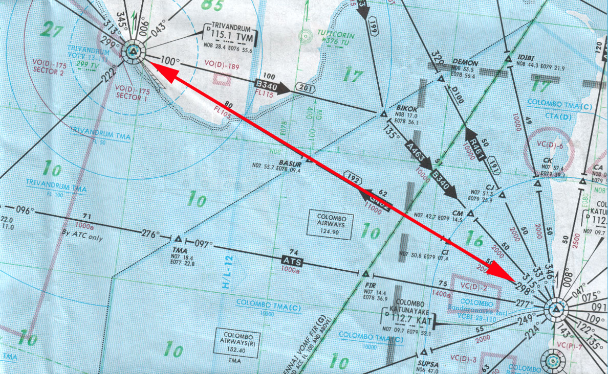
Flight
Route between Katunayaka (VCBI) and Trivandrum (VOTV)
DVOR Range
DVOR
Class= Low Altitude 1,000-18,000 feet Range 40 nautical miles
DVOR
Class=High Altitude 1,000-14,500 feet Range 40 nautical miles
DVOR Class=High
Altitude 14,500-60,000 feet Range 100 nautical miles
DVOR
Class=High Altitude 18,000-45,000 feet Range 130 nautical miles
What
you see in a normal cockpit DVOR display is as follows.
Rotating Course Card is
calibrated from 0 to 360 degrees, which indicates the DVOR bearing chosen as the
reference to fly by pilot.
Omni Bearing Selector or OBS
knob , used to manually rotate the course card to where the point to fly to.
TO-FROM indicator. The
triangle arrow will point UP when flying to the DVOR station. The arrow will
point DOWN when flying away from the DVOR station. A red flag replaces this
arrow when the DVOR is beyond reception.
Course Deviation Indicator
(CDI). This
needle moves left or right indicating the direction to turn the aircraft to
return to course.
The
horizontal dots at center are represent the aircraft away from the course . Each
dot represent 2 degrees deviate from desired course.
The
Airbus DVOR indication a bit different from above and you can view your radial
indication from two displays and looks as follows.

The
diagram on your left has been derived from Digital Distance and Radio Magnetic
Indicator (DDRMI) of A330. VOR (TO) indicate the magnetic bearing to the station
received by VOR (or ADF). The VOR flags indicate
1.Failure
of DVOR receiver 2.DVOR reading is faulty 3.Internal failure of the display
The
diagram on your right has been extracted from Navigation Display (ND) of A330.
VOR needle points towards the current VOR bearing. Bottom needle symbol shows
identifier and tuning.
The
pilot can set DVOR receiver to selected ground station or another word is to
select a radial to define a magnetic course toward or away from DVOR station on
his receiver. As the point 360 is representing Magnetic North, when we called
out, we called in three digits such as 090 that means on the East and 270 means
on the West.
The
proper time to tune navigation receivers is while the aircraft is on the ground
because the pilot has to do the flight planned. After takeoff, usually start
from altitude of 1000 feet minimum above ground level, the DVOR receiver will
get signals from transmitter. When the aircraft has reached to next DVOR station
and DVOR receiver get that signals from next station. At this time, pilot should
select OBS to Radial of next DVOR station.
DME (Distance Measuring Equipment)
While
VOR gives accurate, specific directional information, it cannot make explicit
distance measurements. The pilot, however, may find his distance from the
station by taking an intersection of radials from two VORs, or by doing a timed
radial maneuver with a single VOR. A simpler answer is to use DME which is
associated closely with VOR, the combination providing an accurate position fix.
A special transmitter in the aircraft sends out pulses in all directions and
these are received at the DME station on the ground. As each pulse is received
an answering pulse is automatically transmitted and this is picked up in the
aircraft. It is in fact the reverse of secondary radar.
As
the speed of radio waves is constant at 186,000 miles per second, a computer in
the aircraft which measures the time interval between the transmission of a
pulse and the receipt of the response can convert this time interval into a
distance and display it to the pilot in nautical miles.
It
should be noted, incidentally, that the height of the aircraft affects the
distance measurement; when directly above the station at 36,000 ft the
instrument will show the aircraft as still being six miles from it. This is
because the DME measures slant range rather than ground distance, but it is of
little importance except when very close to the station.
DMEs
are normally co-located with VORs and the frequencies of the two installations
are 'paired'. For example, the VOR frequency of 112.7 MHz is always matched by a
DME on Channel 74, a VOR on 114-9 by a DME on Channel 96 and so on. This means
that aircraft equipment can be arranged so that the selection of a particular
VOR frequency automatically means that the related DME channel is selected at
the same time.
ILS (Instrument Landing System)
ILS
facilities are a highly accurate and dependable means of navigating to the
runway in IFR conditions. When using the ILS, the pilot determines aircraft
position primarily by reference to instruments. The ILS consists of:
Localizer
transmitter
Glide path
transmitter
Outer markers
Approach
lighting system
The
ILS stations are installed in all the international airports, which support the
landing aircrafts with instrument guidance under adverse weather conditions. ILS
is used to provide the pilot, precision information of the aircraft direction so
as he lands the aircraft, if it is possible, to touch the ground in the specific
point. This point should be the centerline of the runway and be at the beginning
of the runway. In addition, aircraft is landed at an angle of 30. So,
the two of the landing guidance (i.e. runway centerline and 30 angle landing
path) are provided by Localizer and Glide path respectively.
The
lateral and vertical guidance is necessary for a pilot to fly a precision
approach, where glide slope information is provided. A precision approach is an
approved descent procedure using a navigation facility aligned with a runway
where glide slope information is given. When all components of the ILS system
are available, including the approved approach procedure, the pilot may execute
a precision approach.
The
system reliability depends upon the equipment maintenance, the installation
quality and the environmental conditions (mountains, buildings, climatologic
conditions). For this reason, there is a theoretical study all the above
conditions, which must not change after the installation.

location of Localizer and Glide path
ILS
stations are classified in the following three categories with respect to the
reliability.
Category I
This
permits the precision aircraft landing in a DH (Decision Height) up to 200 feet,
upwards of the ILS Reference point. The ILS Reference point stands about 150
meters from the aircraft touch down point with the ground.
Category II
This
permits the precision aircraft landing in a DH up to 50 feet, upwards of the ILS
Reference point.
Category III
This
permits the precision aircraft driving in an altitude up to surface of the
landing runway.
At
Bandaranaike International Airport provision is available for category
II.
Localizer
The
primary component of the ILS is the localizer, which provides lateral guidance.
The localizer is a VHF radio transmitter and horizontally-polarized antenna
array that
radiates approximately 100 watts of RF power (between 108.10 MHz and 111.95
MHz). The transmitter and antennas are on the centerline at the opposite end of
the runway from the approach threshold, as seen by the aircraft on approach to
landing. The localizer station radiates a beam of Information indicating the
horizontal centerline of the runway. This beam is produced by two transmitters
operating on the same channel frequency but amplitude-modulated with different
audio signals.
The
localizer station is identified by the transmission of a four-letter
identification code modulated at 1,020 Hz and also by voice identification.
Glide path
Glide
path is a transmitter which gives information of the correct angle slope in
regard with the horizontal level of the straight of aircraft slide, during the
landing.
The
typical glideslope transmitter is usually located 750 feet from the beginning of
the runway and radiates a 5-watt RF signal from a horizontally polarized antenna
array at an inclined glidepath angle of 2.5" to 3.00. The glide slope
transmitter operates on one of 40 available channels provided by 150-kHz spacing
in the UHF frequency range of 329.15 MHz to 335.00 MHz.
Animated version of Glide Path
landing
ILS Marker Beacon and Compass Locator Stations
Marker
Beacons are two or three transmitters which give information about the precision
approach, as control points for the aircraft correct direction of the landing
runway extension. In the above stations is possible are installed and Compass
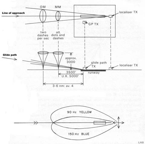
Locators. The Outer Marker (OM) is used to indicate that an aircraft should
intercept the glide path when over the transmitter. The Middle Marker is used to
indicate that the aircraft is at the Decision Height (DH) for most approaches,
and an Inner Marker (IM) is used in Category II or III approaches for the
serious flights.
The
Outer Marker (OM) station, located approximately 4.6 miles from the end of the
runway, amplitude modulates the 75-Mhz carrier at 400 Hz. The OM station is
identified by a 400-Hz audio tone consisting of dashes (approximately 1.5
seconds long), and by the annunciation of a "blue" indicator light on
the cockpit instrument panel.
Located approximately 0.6 miles from the runway is the Middle Marker (MM) station, which amplitude-modulates its 75-MHz carrier at 1,300 Hz. The MM is identified by a 1,300 Hz audio tone consisting of alternate dots (approximately 0.5 second long) and dashes, and the annunciation of an "amber" indicator light in the cockpit.
Radar (RAdio
Detection And Ranging)
There are two types of radar systems installed each
ATC ground station.
The first, called the Primary Surveillance Radar,
operates on the principle of sending a narrow beam of energy, which is reflected
from the aircraft under surveillance, and measuring its distance by noting the
time lapse between the radar pulse transmission and its received echo.
The second, called the Secondary Surveillance Radar,
operates on the coded reply sent from the airborne radio beacon Transponder in
response to an interrogation sent from the ground Radar station. The Radar
station at Piduruthalagala(Sri Lanka), the PSR and SSR antennas are co-located
and scan synchronized, and both radars are used in conjunction to develop the
total air traffic situation display on a single CRT radar scope, called the Plan
Position Indicator (PPI).
Radar controller view of normal Radar display
The Radar station at Katunayaka(Sri Lanka) is a PSR
type and rotate at a speed of 15 revolution per minute while Radar at
piduruthalagala at a speed of 12 rev. per minutes. The reason for this
difference in revolution speed is that, as aircrafts approaches close to the aerodromes
and surrounding airspace needs constant
updates of the positions of the air movements.
Primary
radar has following features
·
It provided only a 2-dimensional position of aircraft , as no altitude
can be detected by such a system
·
Due to reflections on various aircraft around positions were detected but
those of the aircraft to receive services had to be identified. In other words,
this radar cannot understand the who-is-who of what it sees. The controller has
to tell the difference by an identification method usually consisting of track
deviations
·
The identification methods used were cumbersome and with some possibility
of severe errors to happen
·
Almost half of the observed 'targets' on the screen were not the
controlled aircraft and separation between 'known - unknown' traffic was very
important leading to continuous restrictions in maneuvers
·
Apart from aircraft a number of other reflections caused by interference
or hills, obstacles, towers, bridges etc. was cluttering the screens
Plan
Position Indicator (PPI)
Intense
radio contact with pilots was necessary to verify all related ATC elements like
Altitude, Flight level, track, speed etc.
Around
1950-55 and due to similar problems of the military aviation to discriminate the
known (friendly) aircraft from the unknown (enemy) ones , An additional type of
message was added to the existing basic primary radar information by using
another type of equipment .
This
became known as the Secondary Radar and although it did not start as a radar
system it finally developed as one because it had to provide means of
identification of a target at a specific position. Thus, this new device could
provide
·
A 2-Dimensional position and the Flight level of the aircraft which
corresponds to practically a 3-Dimensional position
·
Means of identity by setting a specific signal by the pilot, called SSR
code and then observed by the controller on the screen
The
virtues of the SSR were being proved ever since and when technology stepped into
the computer era the SSR become the 'must' of the ATC for the following reasons
·
It provided a readable label attached to the aircraft position displaying
the full flight number, the Flight level and many other data that one would like
to see as Ground Speed, Direction / Track, Flight Path information and
co-ordination data
·
It helped the quicker and safer Tracking of computer systems of all the
air movements around
·
It proved to be much cheaper which helped the installation of many such
stations
·
It could cover larger distances by about 100-150% covering by far more
wide areas
·
It rejected false reflections due to signal analysis and would provide a
much clearer screen practically without any undesired clutter
Controllers
were extremely happy for this technical achievement as the work was drastically
simplified. Nevertheless, it had to be simplified now because even more the
airspace was becoming congested and the old Primary Radar was showing its limits
as an operational tool.
The VHF Link
and the ADS
Additionally
the Mode-S(which is explained in the particular theory page) had to use this
selective calling (Roll-Call) for known aircraft but at regular intervals had to
interrogate in the classic SSR (All-Call) way just to detect the 'new comers'
into the system yet unknown to it . And even then all linking had to rely on the
radar rotation . That is an instruction to the pilot input by a controller would
have to wait until the radar faces towards the aircraft and then send it .
And
while Mode-S was on the table the satellites gained the floor and impressively
have shown that most of the Air-to-Ground linking can take place simply via the
satellites and standard VHF transmissions. Just like using a mobile phone. The
system becomes then more simple as the aircraft itself can transmit and receive
the data like the user at the other end of a line without depending on the radar
rotation. It also looks cheaper as an idea.
It
was then that Mode-S received a blow on the face and it looked like this would
be its end. Additionally the ADS (Automatic Dependent Surveillance) based again
on the satellites gave a simple solution on the aircraft detection and
communications.
The
position instead of deriving from the radar it could be known simply by a
transmission made by the aircraft itself - by the automatic pilot or rather its
FMS ( Flight management System) .
The
2 solutions competed bravely but the VHF Data-Link appeared first and was
implemented easily while ADS is still on the fight to gain its position in ATC.
Such an experimental VHF-Data Link is existing in MASS UAC of Eurocontrol from
1996 and works in a simple way - at the moment for about 40% of the casual
traffic that is equipped with the new transponders.
Then
people thought of Mode-S differently. Yes, to reduce the need for R/T, the radio
contact between pilot and controller, the VHF Data-Link is better (the concept
of Controller/Pilot Data Link Communications (CPDLC)
is explained
elsewhere in the site). The ADS can replace radar at least in areas impossible
to cover with and may provide a radar display to pilots for self monitoring of
the traffic around for advanced traffic information. Both ADS and CPDLC are
operational in Sri Lanka at the area control center Ratmalana.
Mode-S
is still there with its other advantages:
·
It has place with its 112 pulses for more information than the 2 others
·
It avoids the need for SSR codes
·
It helps the radar tracking to execute a faster and more accurate job
·
And it may work without embarrassing the controller and/or the pilot as
these two will practically do nothing more. Mode-S works on the background
without needing the human intervention.
You
may note however that
Mode-S
is still using radar both as a detection tool as well as a link
A
VHF-Link is used only for communications and replaces the 'natural' R/T only
The ADS tries to replace both - but it is still under development and it is not officially proven yet.
Visit
Radar Theory page for more information about the
operation.
![]()