![]()
Radio
Beacon Transponders
INTRODUCTION
The
site discusses the principles of airborne radio navigation, whereby the pilot
can determine the aircraft's position by triangulation using two ADF or VOR
stations, or by polar coordination using VOR bearing and DME distance
information. Upon request, the pilot can relay the aircraft's position and
altitude to the Air Traffic Control (ATC) center by means of the VHF
communication system. Although this method is effective, it is not an optimum
solution in high-traffic areas where the controller must be constantly informed
of the exact position of all aircraft at all times within the controlled
airspace(Though there is no such higher density of traffic in our region). For
this reason, the ATC center uses a ground-based radar surveillance system to
automatically monitor the location of all aircraft within the control area
without cluttering up the radio communication channels. With this information
constantly displayed on the ATC radar scope, the controller is able to make
timely decisions regarding handing over aircraft to the approach or departure
control center, vectoring aircraft to avoid collision courses, maintaining safe
altitude separation between aircraft, and locating and directing aircraft that
are lost.
The ground-based ATC radar system consists of a primary surveillance radar (PSR) and secondary surveillance radar (SSR). The PSR locates and tracks aircraft within the control area by transmitting a beam of energy which is reflected from the aircraft and returned to the PSR antenna. The SSR transmits interrogation signals to the airborne radio beacon Transponder. Upon receiving the interrogation, the Transponder sends a coded reply signal back to the SSR system. Data received from the PSR and SSR are used in conjunction to develop the total air traffic situation display on the controller's radar scope. This enables the controller to identify Transponder-equipped aircraft in addition to determining the range and direction of all aircraft within the control area.
PRINCIPLES OF ATC RADAR SURVEILLANCE SYSTEM OPERATION
There
are two types of radar systems installed each ATC ground station. The first,
called the Primary Surveillance Radar, operates on the principle of sending a
narrow beam of energy, which is reflected from the aircraft under surveillance,
and measuring its distance by noting the time lapse between the radar pulse
transmission and its received echo. The second, called the Secondary
Surveillance Radar, operates on the coded reply sent from the airborne radio
beacon Transponder in response to an interrogation sent from the ground station.
The Radar station at Piduruthalagala(Sri Lanka), the PSR and SSR antennas are
co-located and scan synchronized, and both radars are used in conjunction to
develop the total air traffic situation display on a single CRT radar scope,
called the Plan Position Indicator (PPI). The Radar station at Katunayaka(Sri
Lanka) is a PSR type and rotate at a speed of 15 revolution per minute while
Radar at Piduruthalagala at a speed of 12 rev. per minutes. The reason for this
difference in revolution speed is that, as aircrafts approaches close to the
airport the sky gets congested and needs constant updates of the positions of
the air movements.
ATC PSR/SSR System
The
PSR sends out radio waves in a very narrow beam. The ground antenna is made to
rotate so that the position of the narrow beam of energy can be directed. When
the directed beam strikes an object or target, some of it is reflected back to
the radar antenna. This reflected signal is detected and processed to provide a
display (indicated by a bright "blip') on the ATC PPI, which shows the
location of the target (i.e., aircraft).
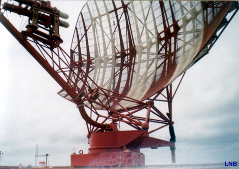
Approach
Radar antenna
The
PSR system works well in low traffic areas; however, as the air traffic
increases in a given area, the PPI display becomes cluttered-and specific
targets may become difficult to distinguish from one another. Also, since the
energy of a radiated RF signal is attenuated as the square of the distance it
travels, the resulting weaker radar returns are accompanied by noise which tends
to obscure the displayed target. Targets may also be lost due to ground clutter
from terrain and precipitation unless a Moving Target Indicator (MTI) circuit is
employed to detect and display only moving objects. Finally, the PSR has the
distinct disadvantage In that the operator has no way of knowing the altitude of
the aircraft unless the pilot reports It. All of the problems associated with
the PSR system have been addressed with the introduction of Air Traffic Control
Radio Beacon System (ATCRBS).
The
ATCRBS incorporates the use of the Secondary Surveillance Radar in conjunction
with the airborne radio beacon Transponder. The SSR was developed from the
military Identification-Friend-or-Foe (IFF) system, in which an airborne radio
beacon Transponder responds to ground radar interrogations on one frequency by
transmitting, coded replies on another frequency. The coded replies, displayed
as short lines on the PPI, allow the controllers to identify the various targets
by having each one send back a different coded reply.
The
desired code can be manually selected by the pilot on the Transponder control
head in Mode W operation, or automatically set by an encoding altimeter or
altitude digitizer for reporting the Aircraft's altitude in Mode "C"
operation. Since the reply signal from the airborne Transponder is stronger than
the reflected PSR signal, it will reinforce the "pip" on the PPI to
provide positive aircraft identification.
At
the ATC radar ground station, received radar video and antenna azimuth
Information signals are relayed from the radar site to the air traffic control
center, where the signals are processed and displayed on plan position
indicators. Since radar coverage of each site includes a large area in high
traffic density areas, several controllers are assigned to various segments of
the area covered. Each controller's segment of the area is displayed on his
respective PPI. (You cannot observe such situation in Sri Lanka due to limited
number of air movements prevail in compared to other countries).
The
PPI presents the operator with a map like view of the space surrounding the area
covered by the ATC radar antenna. Four dots appear on the PPI; one at the
center, and one of each of the three 1 0-mile points out to the edge of the
radar scope. These dots rotate, in synchronize with the rotation of the radar
antenna, to display concentric circles that indicate range.
The
incoming radar video signals are applied to a decoder control before being
displayed. By adjusting the decoder to pass only a selected code, Transponders
operating on the controller's code will appear as a short arc (blip) on the PPI,
and as a bright arc when transmitting a special position identification pulse.
Replies from Transponders not transmitting the selected code will be filtered
out. "Skin-paint" echoes detected by the primary surveillance radar
will be displayed for all aircraft. An illustration of a typical PPI display
format is shown in the figure below.
PRINCIPLES OF RADIO BEACON TRANSPONDER OPERATION
As
previously mentioned, the ATC radio beacon system incorporates the use of the
ground based SSR and the airborne radio beacon Transponder to determine the
range and direction of aircraft responding to SSR interrogations. The following
section will discuss the operation of the airborne Transponder in regard to
receiving these interrogation signals and generating a coded reply signal to be
transmitted back to the SSR ground station.
SSR Interrogation
An
airborne Transponder transmits a reply signal on a frequency of 1,090 MHz in
response to the SSR interrogation which is transmitted on a frequency of 1,030
MHz. Currently, there are two types of SSR interrogations, Mode "K and Mode
"C", that may be transmitted by the ATCRBS ground station. The signal
characteristics of the Mode A and Mode C interrogations are shown in the figure.
SSR Interrogation Modes
Mode
A interrogations are sent to request the specified aircraft identification code.
Mode C Is used to request altitude reporting with identification. Mode B is
occasionally used in place of Mode A in some countries and Mode D in presently
not in use. Each interrogation mode is distinct from the other and is
characterized by the spacing between the P3 pulse and the P1 pulse. Regardless
of the interrogation mode, all three pulses are 0.8 microsecond wide.
The
purpose of the P2 pulse is to allow the Transponder to determine whether the
interrogation was received from the main beam or a side lobe of the SSR
radiation pattern, as shown in the following figure. A reply to a side-lobe
interrogation would give the controller an erroneous indication of the
aircraft's Position. For this reason, Side-Lobe Suppression (SLS) is used to
inhibit the Transponder's reply in response to a side-lobe interrogation.
Propagation
pattern of SSR Interrogation Signal
The
three-pulse SLS interrogation method uses a directional radar antenna that
transmits a pair of pulses referred to as PI and P3 pulses. As previously
mentioned, the time spacing between these pulses determines the mode of
operation. Two microseconds after the P1 pulse is transmitted from the
directorial antenna, the second pulse, P2, is transmitted from an
omnidirectional antenna. The P2 pulse is used as a reference pulse for SLS
determination. The signal strength of the omni-directional P2 pulse is just
sufficient to provide coverage over the area that side-lobe propagation presents
a problem.
Side-lobe
interrogation is detected by the airborne Transponder SLS circuitry by comparing
the amplitude of the P2 pulse in relation to the PI pulse. When the
omnidirectional P2 pulse is equal to or greater than the directional P1 pulse,
no reply will be generated. Identification of the side-lobe interrogation is
established before the P3 pulse is received. Therefore, the Transponder will be
inhibited for a period lasting 35 microseconds, regardless of the interrogation
mode. A valid main-lobe interrogation is recognized when the PI pulse is at
least 9dB larger than the P2 pulse, as shown in the following figure.
Side-Lobe
Detection and Reply Suppression
Transponder Reply Signals
Reply
signals are generated by the Transponder when an interrogation signal is
determined to be valid. The coded reply signal is composed of a series of pulses
transmitted on a carrier of 1,090 plus or minus 3 MHz. In Mode A operation, the
number of pulses generated in a reply signal is determined by setting the four
octal (0 to 7) digit code switches on the Transponder control head to the
assigned identification code. Certain switch positions are reserved for special
applications to cause the activation of an aural alert signal at the
controller's console: Code 7700 indicates an
emergency condition, code 7600 is for reporting a communication radio failure,
and code 7500 indicates that a hijack is in process.
The code selector switches provide the Transponder with the capability to send
any one of a possible 4,096 identification codes.
The Transponder replies to Mode C interrogations by generating pulses in the reply signal that corresponds with the aircraft's altitude. The received altitude information is then displayed directly on the controller's PPI. This information is not selected by the code switches on the control head, but is obtained directly from an encoding altimeter or altitude digitizer. These devices commonly use an optical encoder which is driven from an aneroid mechanism that is sensitive to variations in altitude. The encoder outputs a 1 0-bit parallel data code to the Transponder for the generation of Mode C replies.
The
coded reply signal consists of various arrangements of code pulses within the
boundaries formed by the two framing pulses, F1 and F2. Regardless of the mode
of operation, these framing pulses are always present in the coded reply signal
and are spaced 20.3 microseconds apart.
The reply code is divided into four pulse groups labeled A, B, C, and D. Each group contains three pulses that are assigned subscripts that indicate the binary weight of each. The first digit (1) consists of the Al pulse (=I), the second digit (3) consists of the 131 + B2 pulses (=3), the third digit (2) consists of the C2 pulse (=2), and the fourth digit (4) consists only of the D4 pulse (=4). The assigned reply code-0000 would cause no pulses to appear between the framing pulses, and code 7777 would result in all 12 pulses to be present between FI and F2.
The
Special Position Identification Pulse (SPIP), initiated upon request of the
controller, is generated by momentarily depressing the IDENT button located on
the Transponder control head. The SPIP causes a special effect on the
controller's PPI that aids in determining the aircraft's position. This pulse
occurs 4.35 microseconds after the last framing pulse (F2) and is transmitted
with each Mode A reply for 15 to 20 seconds after releasing the IDENT button.
Principle
of Operation
Radar
is an acronym for Radio Detection and Ranging. The term "radio" refers
to the use of electromagnetic waves with wavelengths in the so-called radio wave
portion of the spectrum, which covers a wide range from 104 km to 1
cm. Radar systems typically use wavelengths on the order of 10 cm,
corresponding to frequencies of about 3 GHz. The detection and
ranging part of the acronym is accomplished by timing the delay between
transmission of a pulse of radio energy and its subsequent
return. If the time delay is Dt,
then the range may be determined by the simple formula:
R
= cDt/2
where
c = 3 x 10⁸ m/s, the speed of light at which all electromagnetic
waves propagate. The factor of two in the formula comes from the observation
that the radar pulse must travel to the target and back before detection,
or twice the range.
A radar pulse train is a type of amplitude modulation of the radar frequency
carrier wave, similar to how carrier waves are modulated in communication
systems. In this case, the information signal is quite simple:
a single pulse repeated at regular intervals. The common radar
carrier modulation, known as the pulse train is shown below. The
common parameters of radar as defined by referring to following figure.

PW
= pulse width. PW has units of time and is commonly expressed in ms.
PW is the duration
of the pulse. RT = rest time. RT is the interval between pulses. It is measured
in ms. PRT = pulse
repetition time. PRT has units of time and is commonly expressed in ms. PRT
is the interval between the start of one pulse and the start of another. PRT is
also equal to the sum, PRT = PW+RT. PRF = pulse repetition frequency. PRF has
units of time-1 and is commonly expressed in Hz (1 Hz = 1/s) or as
pulses per second (pps). PRF is the number of pulses transmitted per second and
is equal to the inverse of PRT. RF = radio frequency. RF has units of time-1
or Hz and is commonly expressed in GHz or MHz. RF is the frequency of the
carrier wave which is being modulated to form the pulse train.
A
practical radar system requires seven basic components.
1.
Transmitter.
The transmitter creates the radio wave to be sent and modulates it to form the
pulse train. The transmitter must also amplify the signal to a high
power level to provide adequate range. The source of the carrier wave
could be a Klystron, Traveling Wave Tube (TWT) or Magnetron. Each has
its own characteristics and limitations.
2. Receiver. The receiver is sensitive to the range of
frequencies being transmitted and provides amplification of the returned
signal. In order to provide the greatest range, the receiver must be very
sensitive without introducing excessive noise. The ability to discern
a received signal from background noise depends on the signal-to-noise
ratio (S/N).
The background noise is specified by an average value, called the noise-equivalent-power
(NEP). This directly equates the noise to a detected power level so
that it may be compared to the return. Using these definitions, the criterion
for successful detection of a target is
Pr
> (S/N) NEP,
where
Pr is the power of the return signal. Since this is a significant
quantity in determining radar system performance, it is given a unique
designation, Smin, and is called the Minimum Signal for Detection.
Smin
= (S/N) NEP
Since
Smin, expressed in Watts, is usually a small number, it has proven
useful to define the decibel equivalent, MDS, which stands for Minimum
Discernible Signal.
MDS
= 10 Log (Smin/1 mW)
When
using decibels, the quantity inside the brackets of the logarithm must be a
number without units. I the definition of MDS, this number is the fraction Smin
/1 mW. As a reminder, we use the special notation dBm for the units of
MDS, where the "m" stands for 1 mW. This is shorthand
for decibels referenced to 1 mW, which is sometimes written as dB//1mW.
In the receiver, S/N sets a threshold for detection which determines what will
be displayed and what will not. In theory, if S/N = 1, then only returns
with power equal to or greater than the background noise will be displayed.
However, the noise is a statistical process and varies randomly. The
NEP is just the average value of the noise. There will be times when
the noise exceeds the threshold that is set by the receiver. Since
this will be displayed and appear to be a legitimate target, it is called a
false alarm. If the SNR is set too high, then there will be
few false alarms, but some actual targets may not be displayed known as a
miss). If SNR is set too low, then there will be many false alarms, or a
high false alarm rate (FAR).
Some receivers monitor the background and constantly adjust the SNR to maintain
a constant false alarm rate, and therefore all called CFAR receivers.
Some
common receiver features are:
1.) Pulse Integration. The receiver takes an average return
strength over many pulses. Random events like noise will not occur in
every pulse and therefore, when averaged, will have a reduced effect
as compared to actual targets that will be in every pulse.
2.) Sensitivity Time Control (STC). This feature reduces the
impact of returns from sea state. It reduces the minimum SNR of the
receiver for a short duration immediately after each pulse is transmitted.
The effect of adjusting the STC is to reduce the clutter on the display in
the region directly around the transmitter. The greater the value of
STC, the greater the range from the transmitter in which clutter will be
removed. However, an excessive STC will blank out potential returns close
to the transmitter.
3.) Fast Time Constant (FTC). This feature is designed to reduce
the effect of long duration returns that come from rain. This
processing requires that strength of the return signal must change quickly
over it duration. Since rain occurs over and extended area, it will
produce a long, steady return. The FTC processing will
filter these returns out of the display. Only pulses that rise and fall
quickly will be displayed. In technical terms, FTC is a differentiator,
meaning it determines the rate of change in the signal, which it then uses
to discriminate pulses which are not changing rapidly.
3. Power Supply. The power supply provides the electrical power
for all the components. The largest consumer of power is the
transmitter which may require several kW of average power. The
actually power transmitted in the pulse may be much greater than 1 kW.
The power supply only needs to be able to provide the average amount of
power consumed, not the high power level during the actual
pulse transmission. Energy can be stored, in a capacitor bank for
instance, during the rest time. The stored energy then can be put
into the pulse when transmitted, increasing the peak power. The peak
power and the average power are related by the quantity called duty cycle, DC.
Duty cycle is the fraction of each transmission cycle that the radar is
actually transmitting. Referring to the pulse train in Figure 2, the
duty cycle can be seen to be:
DC
= PW / PRF
4.
Synchronizer. The
synchronizer coordinates the timing for range determination.
It regulates that rate at which pulses are sent (i.e. sets PRF) and resets the
timing clock for range determination for each pulse. Signals from the
synchronizer are sent simultaneously to the transmitter, which sends a new
pulse, and to the display, which resets the return sweep.
5.
Duplexer.
This is a switch which alternately connects the transmitter or receiver to the
antenna. Its purpose is to protect the receiver from the high power output of
the transmitter. During the transmission of an outgoing pulse, the duplexer will
be aligned to the transmitter for the duration of the pulse, PW. After the pulse
has been sent, the duplexer will align the antenna to the receiver. When the
next pulse is sent, the duplexer will shift back to the transmitter. A duplexer
is not required if the transmitted power is low.
6.
Antenna.
The antenna takes the radar pulse from the transmitter and puts it into the air.
Furthermore, the antenna must focus the energy into a well-defined beam which
increases the power and permits a determination of the direction of the target.
The antenna must keep track of its own orientation which can be accomplished by
a synchro-transmitter. There are also antenna systems which do not physically
move but are steered electronically (in these cases, the orientation of the
radar beam is already known a priori).
The
beam-width of an antenna is a measure of the angular extent of the
most
powerful portion of the radiated energy. For our purposes the main
portion, called the main lobe, will be all angles from the perpendicular
where the power is not less than ½ of the peak power, or, in decibels, -3
dB. The beam-width is the range of angles in the main lobe, so
defined. Usually this is resolved into a plane of interest, such as
the horizontal or vertical plane. The antenna will have a separate
horizontal and vertical beam-width. For a radar antenna, the beam-width
can be predicted from the dimension of the antenna in the plane of interest
by
q = l/L
where:
q is the beam-width in
radians,
l
is the wavelength of the radar, and
L is the dimension of the antenna, in the direction
of interest (i.e. width or height).
In the discussion of communications antennas, it was
stated that the beam-width
for an antenna could be found using q
= 2l/L.
So it appears that radar antennas
have one-half of the beam-width as communications antennas. The difference is
that radar antennas are used both to transmit and receive the signal. The interference
effects from each direction combine, which has the effect of reducing the
beam-width. Therefore when describing two-way systems (like radar) it is appropriate
to reduce the beam-width by a factor of ½ in the beam width approximation
formula.
The directional gain of an antenna is a measure of how well the
beam is focused in all angles. If we were restricted to a single
plane, the directional gain would merely be the ratio 2p/q.
Since the same power is distributed over a smaller
range of angles, directional gain represents the amount by which the power in
the beam is increased. In both angles, then directional gain would be
given by:
Gdir = 4p/q f
since there are 4p
steradians corresponding to all directions (solid angle, measured in
steradians, is defined to be the area of the beam front divided by the range squared,
therefore a non-directional beam would cover an area of 4pR2
at distance R, therefore
4p steradians).
Here we used:
q
= horizontal beam-width (radians)
f
= vertical beam-width (radians)
Sometimes directional gain is measured in decibels,
namely 10 log (Gdir). As
an example, an antenna with a horizontal beam-width of 1.50
(0.025 radians) and vertical
beam-width of 20o
(0.33 radians) will have:
directional gain(dB) = 10 log (4 p/
0.025 0.333) = 30.9 dB
Example:
find the horizontal and vertical beam-width of the AN/SPS-49 long range
radar system, and the directional gain in dB. The antenna is 7.3 m wide by
4.3 m tall, and operates at 900 MHz.
The
wavelength, l=c/f = 0.33 m.
Given that L= 7.3 m, then
q = l/L = 0.33/7.3 =
0.045 radians, or
q = 30.
The antenna is 4.3 m tall, so a similar calculation
gives
f = 0.076 radians
f = 40.
The directional gain,
Gdir = 4p/(0.045 0.076) = 3638.
Expressed in decibels,
directional gain = 10 Log(3638)
= 35.6 dB.
7.
Display. The display unit may take a variety of
forms but in general is designed to present the received information to an
operator. The most basic display type is called an A-scan (amplitude vs. Time
delay). The vertical axis is the strength of the return and the horizontal axis
is the time delay, or range. The A-scan provides no information about the
direction of the target.
Radar
performance
All
of the parameters of the basic pulsed radar system will affect the performance
in some way. Here we find specific examples and quantify this dependence where
possible.
Pulse
Width
The
duration of the pulse and the length of the target along the radial direction determine
the duration of the returned pulse. In most cases the length of the return
is usually very similar to the transmitted pulse. In the display unit, the pulse
(in time) will be converted into a pulse in distance. The range of values from
the leading edge to the trailing edge will create some uncertainty in the range
to the target. Taken at face value, the ability to accurately measure
range is determined by the pulse width.
If we designate the uncertainty in measured range as the range resolution,
RRES, then it must be equal to the range equivalent of the pulse
width, namely:
RRES
= c PW/2
Now, you may wonder why not just take the leading edge of the pulse as the range
which can be determined with much finer accuracy? The problem is that it
is virtually impossible to create the perfect leading edge. In
practice, the ideal pulse will really appear like:
To
create a perfectly formed pulse with a vertical leading edge would require an
infinite bandwidth. In fact you may equate the bandwidth, b,
of the transmitter to the
minimum pulse width, PW by:
PW
= 1/2b
Given
this insight, it is quite reasonable to say that the range can be determined no
more accurately than cPW/2 or equivalently
RRES
= c/4b
In
fact, high resolution radar is often referred to as wide-band radar which you
now see as equivalent statements. One term is referring to the time domain and
the other the frequency domain. The duration of the pulse also affects the
minimum range at which the radar system can detect. The outgoing pulse must
physically clear the antenna before the return can be processed. Since this
lasts for a time interval equal to the pulse width, PW, the minimum displayed
range is then:
RMIN
= c PW/2
The minimum range effect can be seen on a PPI display as a saturated or blank
area around the origin.
Increasing
the pulse width while maintaining the other parameters the same will also affect
the duty cycle and therefore the average power. For many systems, it is
desirable to keep the average power fixed. Then the PRF must be simultaneously
changed with PW in order to keep the product PW x PRF the same. For example, if
the pulse width is reduced by a factor of ½ in order to improve the resolution,
then the PRF is usually doubled.
Pulse
Repetition Frequency (PRF)
The
frequency of pulse transmission affects the maximum range that can be displayed.
Recall that the synchronizer resets the timing clock as each new pulse is
transmitted. Returns from distant targets that do no reach the receiver
until after the next pulse has been sent will not be displayed correctly.
Since the timing clock has been reset, they will be displayed as if the
range where less than actual. If this were possible, then the range
information would be considered ambiguous. An operator would not know
whether the range were the actual range or some greater value.
The
maximum actual range that can be detected and displayed without ambiguity, or the
maximum unambiguous range, is just the range corresponding to a time
interval equal to the pulse repetition time, PRT. Therefore, the maximum
unambiguous range,
RUNAMB
= c PRT/2 = c/(2PRF)
When a radar is scanning, it is
necessary to control the scan rate so that a sufficient number of pulses
will be transmitted in any particular direction in order to guarantee
reliable detection. If too few pulses are used, then it will more difficult
to distinguish false targets from actual ones. False targets may be
present in one or two pulses but certainly not in ten or twenty in a row.
Therefore to
maintain a low false detection rate, the number of pulses transmitted in each direction
should be kept high, usually above ten.
For systems with high pulse repetition rates (frequencies), the radar beam can
be repositioned more rapidly and therefore scan more quickly. Conversely,
if the PRF is lowered the scan rate needs to be reduced. For simple
scans it is easy to quantify the number of pulses that will be returned
from any particular target. Let t represent the dwell time,
which is the duration that the target remains in the
radar's beam during each scan. The number of pulses, N, that the
target will be exposed to during the dwell time is:
N
= t PRF
We
may rearrange this equation to make a requirement on the dwell time for a
particular scan
tmin
= Nmin /PRF
So
it is easy to see that high pulse repetition rates require smaller dwell times.
For a continuous circular scan, for example, the dwell time is related to the
rotation rate and the beam-width.
t
= q/W
where
q = beam-width [degrees] W
= rotation rate [degrees/sec] which will give the dwell time in seconds. These
relationships can be combined, giving the following equation from which
the maximum scan rate may be determined for a minimum number of pulses per scan:
WMAX = q PRF/N
Radar
Frequency
Finally,
the frequency of the radio carrier wave will also have some affect on how
the radar beam propagates. At the low frequency extremes, radar beams will
refract in the atmosphere and can be caught in "ducts" which result in
long ranges. At the high extreme, the radar beam will behave much
like visible light and travel in very straight lines. Very high
frequency radar beams will suffer high
losses and are not suitable for long range systems.
The frequency will also affect the beam-width. For the same antenna size, a
low frequency radar will have a larger beam-width than a high frequency one. In
order to keep the beam-width constant, a low frequency radar will need a large antenna.
Theoretical
Maximum Range Equation
A
radar receiver can detect a target if the return is of sufficient strength. Let
us designate the minimum return signal that can be detected as Smin,
which should have units of Watts, W. The size and ability of a target to
reflect radar energy can be
summarized into a single term, s,
known as the radar cross-section, which has units of
m2. If
absolutely all of the incident radar energy on the target were reflected equally
in all directions, then the radar cross section would be equal to the target's
cross-sectional
area as seen by the transmitter. In practice, some energy is absorbed and
the reflected energy is not distributed equally in all directions.
Therefore, the radar cross-section is quite difficult to estimate and is
normally determined by measurement.
Given these new quantities we can construct a simple model for the radar power
that returns to the receiver:
Pr
= Pt G 1/4pR2
s
1/4pR2
Ae
The
terms in this equation have been grouped to illustrate the sequence from
transmission to collection. Here is the sequence in detail:
G
= r Gdir
The
transmitter puts out peak power Pt into the antenna, which focuses it
into a beam with gain G. The power gain is similar to the directional gain, Gdir,
except that it must also include losses from the transmitter to the antenna.
These losses are summarized by the single term for efficiency, r. Therefore
The
radar energy spreads out uniformly in all directions. The power per unit area
must therefore decrease as the area increases. Since the energy is spread out
over the surface of a sphere the factor of 1/4pR2 accounts for the
reduction.
The
radar energy is collected by the surface of the target and reflected. The radar
cross section s accounts for both of these processes.
The
reflected energy spreads out just like the transmitted energy.
The
receiving antenna collects the energy proportional to its effective area, known
as the antenna's aperture, Ae. This also includes losses in the
reception process until the signal reaches the receiver. Hence the subscript
"e" for "effective." The effective aperture is related to
the physical aperture, A, by the same efficiency term used in power gain, given
the symbol r. So that
Ae
= r A
Our
criterion for detection is simply that the received power, Pr must exceed
the minimum, Smin. Since the received power decreases with
range, the maximum detection range will occur when the received power is
equal to the minimum , i.e. Pr = Smin. If
you solve for the range, you get an equation for the maximum theoretical radar
range:
Perhaps the most important feature of this equation is the fourth-root dependence. The practical implication of this is that one must greatly increase the output power to get a modest increase in performance. For example, in order to double the range, the transmitted power would have to be increased 16 times. You should also note that the minimum power level for detection, Smin, depends on the noise level. In practice, this quantity constantly be varied in order to achieve the perfect balance between high sensitivity which is susceptible to noise and low sensitivity which may limit the radar's ability to detect targets.


![]()