Report
of the Commission of Inquiry appointed by HE the President to inquire into the
causes and circumstances in which Loftleider Icelandic Airways Aircraft DC-*-63F
TF-FLA met with an accident in he vicinity of the Katunayake Airport on 15th
November 1978
SECTION
I
1.
Terms of Reference of the Commission
HIS
EXCELLENCY J. R. JAYEWARDENE
PRESIDENT
OF SRI LANKA
YOUR
EXCELLENCY,
ON
November 25, 1979, Your Excellency issued to me a Commission in pursuance of the
provisions of Section 2 of the Commissions of Inquiry Act (Chapter 393), with
the following terms of reference :
(1)
To inquire into and report on the causes and circumstances in which the aircraft
bearing registration No. TF-FLA and belonging to Loftleider Icelandic Airways
met with an accident in the vicinity of Katunayake Airport at about 23.30 hours
local time on November 15, 1978
(2)
To consider whether any degree of responsibility for the aforesaid accident may
be attributed to any person and
(3)
To recommend what steps, if any, should be taken to ensure the avoidance of
similar accidents in the future.
2.
Synopsis
2.1.
On November 15, 1978, Icelandic Airlines Flight LL 001 a DC-8 63 CF (TF-FLA)
which was being operated as a charter passenger flight, took-off from Jeddah
Airport, Saudi Arabia, at approximately 12.58.03 z to proceed to Surabaya,
Indonesia, with a programmed technical stop at Colombo Airport, Katunayake (CAK),
Sri Lanka, for fuel and crew change. The aircraft had been chartered by GARUDA
Indonesian Airways to carry Indonesian " Haj " pilgrims from Indonesia
to Mecca and return. The aircraft contacted Area Control, Ratmalana, at 22.53.24
local time and was informed that the runway in use at Colombo Airport,
Katunayake, was 04. The aircraft requested runway 22 and accordingly was cleared
for a radar vectored Instrument Landing System (ILS) approach to runway 22. Area
-Control who was in contact with the aircraft initially descended the aircraft
from FL (flight level) 330 to FL 220 approximately 90 miles out of Colombo
Airport, Katunayake. The aircraft was then handed over at 23.06.32 to the Radar
Control (CAK) under whose instructions it descended to FL 20 to make an ILS
approach to runway 22. The aircraft followed the Controller's instructions and,
to all appearances, was making a normal ILS approach to runway 22. The Radar
Controller also requested the aircraft to report when it was established on the
Localizer, but, though the request was acknowledged, no confirmation was
received. The Radar Controller continued to give advisory information on the
aircraft's distance and height, the last advisory call being at 23.27.26 when
the aircraft was informed thus
"
Lima, Lima 001, slightly to the left of centre line, very slightly to the left
of centre line, two miles from touch-down, height 650 feet, cleared to land-off
this approach."
This
transmission was acknowledged by the aircraft at 23.27.37 in the manner "
Roger ". There was no further communication from the aircraft.
2.2.
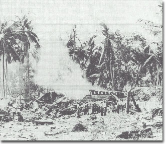
Shortly thereafter, the Approach Controller (CAK) sighted the aircraft very low
on the approach and called out twice "Lima, Lima 001, you are undershooting
". However, this transmission was not received by the aircraft as the
Approach Controller spoke on the approach frequency 119.7 MHz whereas the
aircraft was still tuned to the Radar Controller on 119.1 MHz. The Approach
Controller observed the aircraft disappearing from sight followed by what
appeared to be a ball of fire around the area where it passed out of sight. The
aircraft had crashed into a rubber and coconut plantation at a point 1.1589 n.m.
from runway 22 threshold, 103.15 feet to the right of the extended centre line
of the runway. The aircraft was destroyed by impact and fire.
2.3.
The Approach Controller on duty was the first to observe the crash, and the
Radar Controller, Area Controller and others were immediately notified of the
accident by him.
3.
Rescue Activities
3.1.
Rescue activities commenced within half an hour of the accident and
fire-fighting units were in attendance from this time onwards. Around 5
fire-fighting units were in attendance and the whole operation was coordinated
satisfactorily. The main section of the fuselage that was intact was under
intense fire and considerable effort was required to bring the fire under
control by which time all occupants of this section of the aircraft had
succumbed due to fire. Fire-fighting activity was hampered as ready access to
the site of the crash was not possible due to the large number of coconut trees
that prevented large units from getting closer to the Wreckage.
3.2.
The Acting Director of Civil Aviation was personally present with the members of
his staff and participated in the rescue operations along with the police and
airport staff. The rescue operations were subsequently highly commended by the
representatives of the Indonesian and Icelandic Governments.
3.3.
All cockpit instruments found among the wreckage were photographed before being
handled by anyone and were taken charge of by the Acting Director of Civil
Aviation who handed them over to the office of the Defense Ministry to be kept
under security. The seals of the packages were broken in my presence at the
inquiry.
SECTION
II
4.
Injuries to Persons
4.1.
The injuries to persons were as follows :
Injuries
Crew Passengers
Others
Fatal
8
175
0
Non-fatal
4
28
0
None
1
46
0
5.
Notifications to Interested Parties
5.1.
The State of Registry of the aircraft, namely, Iceland, the State of~
Manufacture of the aircraft, namely, the United States of America, the State of
maximum number of fatalities, namely, Indonesia, were all informed of the
accident. They sent their accredited representatives who made their own
preliminary fact-finding investigations and returned to their respective States.
The Department of Civil Aviation gave them its full co-operation in the conduct
of such investigations.
6.
Read-out of Recordings
6.1.
At the time of my appointment as Commissioner, only the Icelandic team was still
in this country and I had several informal discussions with them in regard to
the investigation. Before formal sittings could be held for the recording of
evidence of witnesses, it was necessary to send three instruments recovered from
the wreckage of the aircraft, namely, the Flight Data Recorder (FD R) (commonly
called the Black Box), the Cockpit Voice Recorder (CVR) and the Kifis Box (KB),
to appropriate centres abroad for a read-out of the recordings as there are no
facilities locally for that purpose. The FDR and CVR were sent to the Air Safety
Investigation Branch of the Department of Transport in Melbourne, Australia, and
the Kifis Box to the manufacturers in the United States of America.
7.
Formal Sittings
7.1.
Fifteen formal sittings were held during the period 12th March to 6th April. The
records of the proceedings are forwarded separately.
7.2.
All the interested parties were given due notice of the formal sittings.
7.3.
Mr. Skuli Jon Sigurdarson was present throughout the sittings as the accredited
representative of Iceland and participated in the proceedings assisted by Mr.
Jon Oltarr Olafsson, Capt. Skuli Br. Steinthorsson an~ Mr. Johannes Jonsson
representing the Icelandic Airlines.
Mr.
1. R. Soepartolo was the accredited representative of Indonesia and was assisted
by Mr. Soewardi. He was present at most of the sittings and participated in the
proceedings.
Mr.
D. H. Athulathmudali, Acting Director of Civil Aviation of Sri Lanka was present
throughout the sittings and participated in the proceedings.
The
State of Manufacture of the aircraft, namely, USA, was not represented at the
inquiry though due notice was given.
Mr.
V. C. Gunatilaka, Solicitor-General, assisted the Commission as Legal Adviser
and Mr. D. J. Rosa, Assistant Director of Civil Aviation (Aeronautical
Inspections), as Technical Adviser.
Mr.
G. P. S. U. de Silva, Senior Assistant Secretary of the Ministry of Defence,
functioned as Secretary to the Commission.
8.
Public Representations
8.1.
Newspaper advertisements calling for public representations were inserted in the
leading local newspapers. A number of letters were received in response to these
advertisements but none of them merited consideration. The writers of those
letters were not called to give evidence.
SECTION
III
9.
Navigational Aids
The
navigational aids installed at Katunyaka Airport and their status, at the time
of the accident are as follows:
9.
1. VISUAL AIDS:
(a)
Visual Approach Slope Indicator (VASI).-VASI is a very useful pilot aid. It is
of various types. In the type fitted at Katunayake airfield, bars of red and
white lights on each side of the runway are so beamed by reflectors that when a
pilot is too low he sees all red lights ; when he is too high he sees all white
lights ; and when he is on the correct approach path he sees red and white bars
one above the other.
The
VASI was in satisfactory working order on the night of the accident.
b)
Approach Lighting.-The Approach Lighting System gives guidance to aircrafts in
the landing phase assisting them in aligning correctly with the runway centre
line.
This
system had been unserviceable for some months prior to the date of the accident
and this fact had been brought to the notice of all airmen by the issuance of a
" notam " in accordance with the international practice.
The
pilot of flight LL 001 would have been aware of the non-availability of the
approach lights. At the time of the accident he was correctly aligned on the
centre line by other means and as he was already in sight of the runway lights
and of the VASI, the non-availability of the Approach lighting System had no
bearing on the accident.
(c)
Runway Lights.-The Runway Lighting System was in operation at the time of the
accident. The cockpit voice recording indicates that two different voices had
mentioned on four occasions that Capt./Co-Pilot " had been visual ".
This term implies that ' the Capt./Co-Pilot had seen the runway lights while
making the approach to land.
9.2.
Radio Navigational Aids:
(a)
Very High Frequency Omni-directional Radio Range (VOR).-This was in operation at
the time of the accident and there was a remote indicator at the Control Tower
to indicate the serviceability of the unit. This aid is of little importance
other than to get some rough guidance to align the aircraft with the runway
centre line. In the instant case, however, this had been done by the use of the
radar.
(b)
Distance Measuring Equipment (DME).-At the time of the accident this had been
unserviceable for over two months and had been notamed " to that effect. At
Katunayake the DME is co-located with the VOR which is not on the extended
centre line of the runway. It is useful as a landing aid only if it is
co-located with the Glide Path Equipment as is sometimes done in some countries.
The function of the DME is for en route navigation purposes. Its
unserviceability on the night of November 15 had no bearing on the accident.
(c)
Non-Directional Beacon.-The Non-Directional Beacon installed at the airport
(NBD-KAT) was in operation at the time of the accident. As the aircraft was
correctly aligned on the extended center line of the runway it was of no further
importance to the landing of the aircraft.
(d)
Non-Directional Beacon at Yakwila (NDB-YKW).-The Non-Directional Beacon at
Yakwila is located on the extended centre line of the runway and was in working
condition at the time of the accident. The location of this NDB is approximately
17 miles from the end of the runway. As the aircraft was correctly aligned on
the extended centre line by other means, it was of little importance to the
landing phase of the aircraft.
(e)
Instrument Landing System (ILS).-This is by far the most important radio
navigational aid associated with the landing phase of an aircraft. It was
available to aircraft making an approach to runway 22.
9.3.
The ILS comprises the following basic components :
(i)
VHF Localizer Equipment (LOC), associated monitor system, remote control and
indicator equipment,
(ii)
VHF Glide Slope or Glide Path Equipment (GS), associated monitor system, remote
control and indicator equipment ;
(iii)
Two VHF Marker Beacons, namely, the Outer Marker and Middle Marker (OM and MM),
associated monitor systems, remote control and indicator equipment.
The
system is operated electronically. The Localizer is a thin beam in the vertical
plane and provides correct guidance to align the aircraft on the extended centre
line of the runway. The beam comes from a very high frequency (VHF) transmitter
at the far end of the runway on the centre line. The pilot sees it as a vertical
needle on his ILS instrument.
The
Glide Slope (or Glide Path) is a thin beam in the horizontal plane. It provides
electronic guidance defining a 3' glide angle and keeps the pilot on the correct
descent path. The pilot sees it as a horizontal needle on his ILS instrument.
By
flying the aircraft so that the needles are exactly crossed-" locked on the
pilot keeps the aircraft on the correct landing approach.
The
Marker Beacons located on the extended centre line and away from the airport at
a distance of 5 n.m. and 3,500 feet respectively from the threshold ,of the
runway 22, provide vertically generated information which can be picked up in
the aircraft only when it is overhead of the respective beacons.
9.4.
In the Control Tower is situated the remote control and indicator equipment of
each of the components which would indicate to the Controller the operational
status of the respective components at any time. The indicator would show a
green light if the particular component was functioning properly and a red light
if it was not. On the night of the accident only the indicator in respect of the
Localizer was serviceable. The cable connecting the Glide Slope to the indicator
unit was broken and, therefore, the signal that should be received from the
monitor of the Glide Slope was not received in the indicator unit. The indicator
of the Glide Slope, therefore, constantly showed a red light irrespective of
whether the Glide Slope was properly functioning or not. According to the
evidence led before me, information as to whether the Glide Slope was
functioning properly or not was furnished to the Controller at the tower by a
radio technician who was in charge of an ILS portable receiver in a room on the
lower floor of the building. It was the duty of that technician to monitor the
portable receiver and to communicate immediately to the Tower Controller if the
glide slope equipment had shut down or was malfunctioning.
9.5.
The cables connecting the two Marker Beacons were also missing (as they were
being constantly stolen) and the Controller at the tower had no means of knowing
whether they were functioning or not.
On
the night of November 15, the aircraft crashed after passing the Outer Marker
and before reaching the Middle Marker. Consequently, the status of the Marker
Beacons that night had no bearing on the accident.
9.6.
One of the matters~ that requires consideration and which became controversial
during the course of the inquiry is whether the Glide Slope was working properly
on the night of November 15, or whether it was the malfunctioning of the Glide
Slope that was the cause or one of the causes of the accident. I shall deal with
this matter later on in this report.
SECTION
IV
10.
Course of the Flight
10.1.
The aircraft contacted Area Control Centre, Colombo, at 22.53.24 local time and
was informed that the runway in use at Colombo Airport, Katunayake (CAK) was 04
and was also given particulars of the weather. The aircraft inquired whether
runway 22 was available. (Runway 22 is the one on which the use of the ILS was
available). Area Control confirmed the availability of runway 22 and immediately
afterwards at 23.00.48 the pilot confirmed his decision to use runway 22.
10.2.
At 23.01.51 meteorological information regarding the cloud base was passed on to
the aircraft subsequent to which the aircraft requested the Madras weather.
Sometime later, Area Control obtained the Madras weather from Madras and
furnished it to the aircraft at 23.18.40.
'10.3.
At 23.03.47 the aircraft reported " standing by for. descent " upon
which Area Control cleared it for descent to FL 290. At 23.06.09 it was
descended further to FL 220.
10.4.
Colombo radar took over control of the aircraft around 23.07.00 when it was 90
n.m. out. At 23.10.17 clearance to descend to 7,000 feet was given to the
aircraft, and at 23.11.21 a distance call of 60 n.m. was given by the Radar
Controller.
10-5.
The next radar call was at 23.10.13 when the aircraft was informed by the Radar
Controller that it would be a radar vectoring to the ILS on runway 22 and that
there was a " bit of weather " on the approach but that visibility was
reported to be 6,000 meters. A further clearance to descend to 5,000' was given
to the aircraft at 23.17-30 and to 3,000' at 23.22.08. At 23.23.41 it was
recleared to 2,000' and a heading of 180 was given.
10.6.
In response to an inquiry from the aircraft " Is the ILS working now ?
" around 23.24.00 the R/C replied " affirmative " and went on to
inform the aircraft " You are closing the localizer from the right, 12
miles from touch-down, recleared to 2,000r.
10.7.
Whilst lining up on finals at 23.25.23 the aircraft was informed that it was 8
in. from touch-down and was given a heading change of 220. Seventeen seconds
later it was instructed to commence a descent to maintain a 3' glide path with
the information that it was 7j miles from touch-down. At 23.25-55 the Radar
Controller requested the aircraft to report when it was established on the
localizer or when runway was in sight and this call
by
the aircraft as " Roger ".
10.8.
The next call from Radar was at 23.26.15 after the aircraft had lined up with
the centre line of runway 22 when the Radar Controller advised, ,,You will
approach the outer marker in 25 seconds". This call was acknowledged by the
aircraft as " Roger " at 23.26.28.
10.9.
At 23.26.52 the aircraft was informed by Radar that it was 4 miles from
touch-down and at a height of 1,300', being cleared to land off the approach to
runway 22. This clearance was acknowledged by the aircraft at 23.27.00.
10.10.
The next advisory call was given by Radar at 3 miles with height particulars of
1,000' at 23.27.10.
10.11.
Radar gave the next call at two miles at 23.27.26 in the following manner,
" Lima, Lima 001, slightly to the left of centre line, very slightly to the
left of centre line, two miles from touch-down, height 650', cleared to land off
this approach." This was acknowledged by the aircraft, at 23.27.37 as
"Roger".
10.
12. A further final call to the aircraft by Radar " Slightly to the left of
centre line " at 23.27-49 went unacknowledged.
10.13.
At 23.28.03 the aircraft crashed 1.1589 n.m. from the threshold of runway 22
11.
Impact Sequence and Wreckage
11-1.
The impact occurred in an area along the extended centre line of runway 22, the
initial contact with coconut-trees being at a height of 163' above mean sea
level, 103.15' to the right of the centre line of runway 22. This area was
planted with coconut trees, the aircraft brushing the tops of five coconut trees
whilst traversing the last 99 feet of the coconut plantation. On leaving the
coconut plantation the aircraft entered the rubber plantation almost in a level
altitude and passed through the rubber tree tops without an appreciable change
in elevation but progressively banking to the Port, the bank angle on leaving
the rubber plantation being approximately 20 degrees. Whilst traversing the
rubber plantation the aircraft cut a path through the trees approximately 429
feet long and 112 feet wide at the widest point. The Port wing-tip and area
immediately after it progressively disintegrated whilst passing through the
rubber trees. The aircraft then entered the second coconut plantation and
traveled in a slightly descending altitude, the bank to Port increasing
progressively up to around 40 degrees over a distance of approximately 396 feet
at which point the ground impact marks commenced. The marks on the ground
extended to almost 360 feet around which point the aircraft cart-wheeled to the
starboard. Whilst cart-wheeling, the Port engines were shed, and the fuselage
section from around 12 feet forward of the centre section up to the cockpit
sheared away and continued along the path of travel, progressively breaking up
into six sections and piling up in one heap approximately 478 feet from the
point of initial contact with ground of the aircraft. The remainder of the
fuselage, port and starboard wings of the empennage continued to move in a
sweeping motion, the tail section approximately 30 feet above ground finally
coming to rest almost on the centre line of the runway on a heading 070/290
facing the east. The tail section of the rear galley broke off at this stage and
the starboard engines were shed immediately prior to the final resting of the
fuselage. A fire ensued in the main fuselage section.
11.2.
The port wing-tip and the wing-tip attachment areas were demolished at the
initial impact within the rubber plantation. The port wing continued to break
down progressively as the aircraft traversed through the rubber and coconut
trees up to the point of impact with ground. Other than the port wing, the rest
of the aircraft did not suffer any damage up to this point. The breaking up of
the fuselage and empennage occurred after the ground impact. During the
examination of the wreckage, all flying controls and components were identified
ruling out the possibility of any pre-crash failure of the structure. The fire
that engulfed the main fuselage section burnt down the fuselage up to window
level. There was no fire in the forward area which accounted for most of the
survivors being from the forward section.
SECTION
V
12.
Instruments Recovered and Readings
Although
the cockpit area was broken up into sections certain instruments were located
and taken charge of, the principal ones being the following :
12.1
Flight Data Recorder (FDR).-The Flight Data Recorder was recovered in an
undamaged condition on the morning after the accident from the wreckage strewn
around the tail area of the aircraft.
12,2,
Cockpit Voice Recorder (CVR).-The Cockpit Voice Recorder was. recovered in a
slightly damaged condition on the morning after the accident from the
undergrowth around the area where the wreckage of the tail section of the
fuselage was scattered. The unit was in a relatively undamaged state.
12.3.
Course Indicator (Captain's Panel).-This instrument showed the following
readings
(a)
Course Indicator-210 degrees
(b)
Course Bug set at 220 degrees
(c)
Deviation Needle .75 dots to the left
(d)
Glide Path Needle .5 dots above aircraft position
(e)
Glide Slope Flag out of view;
(f)
LOC Flag out of view
(g)
Compass Flag in view.
12,4.
Flight Director Display (Captain's Panel).-The readings as follows :
(a)
V-Command Bars-showing marked fly-up ;
(b)
Rising Runway-almost in contact with aircraft
12.5.
Radio Altimeter (Captain's Panel).-This instrument showed
following readings
(a)
Flag-out ;
(b)
Bug set at 150'
(c)
Altitude Indicator-120'.
12.6.
Pressure Altimeter (Captain's panel).This was set at 1014mbs reading 250'.
12.7.
VHFNAV-Captain -
116.3011z
CO-Pilot
- 110.30Hz
VHFCOM-Captain
- 118-97
CO-Pilot
- 131.50
12.8.
Flight Director Control Panel
Mode Switch-GA
Altitude Control Switch-off
Pilot Control-0 degrees
13.
Read-out of Instruments
13.1.
The Flight Data Recorder was taken to the Air Safety Investigation Branch of the
Department of Transport, Melbourne, Australia, where a satisfactory read-out was
obtained.
13.2.
Cockpit Voice Recorder.-This was also sent to the Air Safety Investigation
Branch of the Department of Transport, Melbourne, Australia, for a read-out. The
cartridge of the Voice Recorder was found in an undamaged condition and was
played back on the special equipment available at the ASIB. A copy of the report
of the Board is annexed. Of the half hour recording available on the CVR a large
percentage of the conversation was in Icelandic. Recordings of the four channels
on the cartridge were made individually and collectively and given over to the
Icelandic delegation for translation. A certified translation in English of the
read-out as furnished by the Icelandic delegation is Annex III. Certain
amendments to this certified 'translation were effected by the delegation in
March 1979 during the course, of the proceedings.
13.3.
Control Tower Tapes.-A recording of the VHF communications between Area Control,
Radar Control and the aircraft was available and an accurately timed transcript
of this was made out, extracts of which were superimposed on the Final Approach
Profile Diagram.
13.4.1.
Reconstructed Approach Profile (Annex V).-The Reconstructed Approach Profile was
drawn using data computed from the FDR read-outs. The FDR is an old type giving
only five parameters and the ground speed cannot be obtained directly. The
computation of the Distance Axis (Axis X) on the Approach Profile graph is
dependent on accurately knowing the ground speed, which is the vector sum of the
indicated air speed (IAS) and the speed of the wind relative to ground (or air
speed).
13.4.2.
The wind component used was zero as the wind, according to the meteorological
report at the time of accident, was " 120 degrees 07 " which meant a 7
kt wind was prevalent from direction 120 degrees. As the approach heading was
220 degrees the component of this wind along the approach path was reckoned to
be almost zero.
13.4.3.
The nominal glide slope is 3 degrees and the lower broken line on the drawing is
the worst assumed glide slope at 1.48 degrees to the horizon. The curve at the
top of the drawing is the descent rate. The text appearing above the nominal
glide slope in cages is from the CVR transcript and the text below the glide
slope in cages is from the Control Tower tapes. The figure in the cages
alongside the conversation is local time.
13.4.4.
The impact point 'x' is at 163' above mean sea level.
13.5.
A cross section of the Approach Profile prepared by the Icelandic delegation
with a wind component of 0.
14.
Superimposed Transcript
A
superimposed transcript was made combining the Control Tower tapes transcription
and the CVR transcripts. This appears as Annex VII to this report. The contents
of the transcript provided valu4ble, information for the, analysis.
SECTION
VI
15.
Approach Procedures
The
more important of the procedures laid down in the Loftleider Icelandic
Operations Manual for Approach and Landing as appearing at pages 4.3.27, 4.3.28,
4.4.18 and 4.4.19 are set out below. The ILS at Katunayake being only of
Category 1, the approach procedures set out for automatic approaches under
Section P at pages 4.4.19 and 4.4.20 are not applicable.
(a)
After passing through 18,000' or transition altitude, select the P.T.C. to
" override " and maintain 2,000 setting on the Radio Altimeter until
passing 2,000' above the ground and observing the light ON at which time the
minimum descent altitude or decision height may be set.
(b)
The Co-Pilot will set the Altitude Alerting System to indicate clearance limit
altitude throughout the descent and clearance to landing.
(c)
The Co-Pilot will note and announce altitude 1,000' prior to reaching the
clearance limit altitude.
(d)
Use positive, not excessive rate of descent right down to the minimum descent
altitude.
(e)
At the outer marker and at 500' above the runway threshold altitude the Pilot
not flying the aircraft will cross-check both sets of flights, instruments for
proper comparison and ascertain that no warning flags are in view.
(f)
If the flying instruments are normal, he will announce 'no flags'. He will also
announce the airspeed in relation to Vref (Threshold Speed) and the rate of
sink. Example :
Outer
Marker
500 ft.
No
flags
No flags
Ref
+ 10
Ref +10
Sink
900
Sink 600
(g)
Notification will also be made when
(1)
passing through 1,000',
(2)
leaving 500',
(3)
passing through 100' above minima,
(4)
at minima, and
(5)
approach lights in sight.
Only
the altitude need be called out, unless deviation from desired speed, track or
glide path is noted.
SECTION
VII
16.
Failure of the Crew to Adhere to Laid Down Procedures
16.1.
A perusal Of the Control communication/CVR transcript and the Approach Profile
(Annexes V and V11) indicates that the crew in command failed in many respects
to adhere to the procedures laid down.
16.2.
The Co-Pilot had not announced the altitude 1,000' prior to reaching the
clearance limit altitude (vide 15 (c) above).
16.3.
The call-out of altitudes when passing through 1,000', leaving 500', passing
through 100' above MDH and at MDH (vide 15 (g) above) had not been made.
The
call at MDH is a most important call as this height is the lowest altitude that
the pilot descends to if he cannot see the runway and he must stay at this
altitude, not lower, until he has visual contact with the runway and, if not
visual, he should go around (overshoot) and make another approach.
16.4.
At the outer marker and at 500' the standard announcements that to be made
regarding
(i)
the indication from his scan for warning flags,
(ii)
the speed in relation to desired threshold speed, and
(iii)
the sink rate
were
not called.
The
failure to monitor the sink rate was a grave lapse which was a contributory
factor to the accident. Considering the average ground speed of the aircraft and
its gross weight during descent, the appropriate rate of descent would have been
850/900' per minute. The rate of descent appearing on the top of the Approach
Profile (Annex V11) indicates that the rate of descent whilst being on the high
side for most of the approach has been well above 1,000'/min. on five peak value
excursions, the maximum rate of descent being its high as 2,000'/min. and
1,800'/min. in the final phase of descent.
16.5.
The rates of descent of 1,800' to 2,000'/min. are excessive especially at such a
late stage on the final approach when the crew had lost visual contact with the
runway and were approaching the minima for that runway. This situation could
have been avoided if the crew had adhered to the laid down procedures (vide 15
(d)).
16.6. The Icelandic team sought to find an excuse for the failure of the crew to call out the altitudes, the sink rates and Vref deviations by stating that the Co-Pilot was busy complying with the Captain's instructions and had no time to make the aforesaid vital call-outs. An efficient crew member will never miss important calls at critical stages of any approach, however, heavy his work-load may be, as he should know that non-compliance may result in the aircraft and the passengers being placed in jeopardy. it is not clear why the Company procedure does not provide for the Flight Engineer being utilized to monitor important procedures and call-outs during approach when the Co-Pilot is busy otherwise. In any event, if the procedures had been strictly followed, there should have been no clash between the Co-Pilot's carrying out the Captain's orders and making the call-outs expected of him.
SECTION
VIII
17.
Information Furnished by the Radar Controller
17.1.
The point was raised that there was discrepancy in the position data passed on
to the aircraft by the Radar Controller ; that when the R/C gave the call "
4 miles out at 1,300' " the position of the aircraft according to the
Approach Profile (Annex V11) was 4.2 miles out at 1,640' ; similarly, when the
call was " 3 miles out at 1,000"' the position of the aircraft was 33
miles out at 1,290' ; and when the call was " 2 miles from touch-down at
650"' the position of the aircraft was 2.77 miles out at 1,020' ; and that
the Captain's excessive rates of descent at those points were probably due to
his anxiety to conform to the calls given by the R/C. It was thus sought to lay
the blame on the R/C for the excessive sink rates at those points. It should be
noted that the excessive sink rates were not confined to those points alone.
Apart from that, one may consider whether the blame for the excessive sink rates
can be reasonably passed on to the R/C.
17.2.
The aircraft was cleared for an ILS approach to runway 22 by the R/C at 23.16.13
and the R/C informed the aircraft that it was a " radar vectoring to ILS
". The principle of a radar vector to the ILS is " to provide radar
vectoring of arriving traffic on to pilot-interpreted final approach aids "
(ICAO DOC 4444 Rules of Air Traffic Services, P. 10). The radar vector to ILS
positively terminates once an aircraft is established on the ILS. The Captain,
therefore, once he was established on the ILS should and would have known that
further radar vectoring was unnecessary and superfluous ; that he was no longer
under the control of the R/C and that he was not obliged to take note of any
advisory information given to him by the R/C.
17.3.
The R/C had at 23.25.25 instructed the aircraft to report when it was
established on the localizer or when runway was in sight. The crew had however,
failed to report at any stage that they were established on the localizer or
that runway was in sight and consequently the R/C appears to have continued ,to
give advisory heights. This subsequent advisory information was definitely not a
part of the radar vectoring to the ILS as the aircraft was already established
on the localizer. Had the aircraft reported established on the localizer or had
the runway in sight the R/C would have terminated the vectoring and handed -over
the, aircraft to the Tower Approach Controller for the final approach and
touch-down. It was primarily the Captain's failure to report that he was
established on the localizer that was responsible for the aircraft not being
handed over to the Tower Approach Controller at the proper time.
Apart from the fact that he was not under any obligation to take note of
the superfluous advisory information that was continuing to be furnished to him
by the R/C, the Captain could have checked his own altimeters before accepting
the heights furnished by the R/C and acting on them. The Pilot should have known
that it was not a Surveillance Radar Approach (SRA) that he was following. If
the readings on his altimeter did not tally with the information furnished by
the R/t, the R/C's information should have been ignored. It was also open to the
Captain to bring to the notice of the R/C that the altitudes furnished by him
did not tally with the readings on his altimeters and to have
asked for confirmation. In
all the circumstances, I do not think it reasonable pass on to the R/C the blame
for the excessive sink rates of the aircraft.
17.4.
The Icelandic team marked in evidence a Flight Path cross section with wind
component + 10) and submitted that
the aircraft was always farther
away from the runway touch-down point than specified by the Radar Controller.
According to them, when the Radar reported the aircraft to be 4 n.m. from
touch-down and the altitude to be 1,300' the aircraft was actually at 4.5 n.m.
and at an altitude of 1,530' ; when Radar reported 3 n.m. and an altitude of
1,000' the aircraft was about 3.7 n.m. at 1,200'; and when Radar reported 2 n.m.
and the altitude to be 650' it was in fact at 2.8 n.m. and 870' altitude. It
will be noted that the figures given by the Icelandic team on the basis of Annex
VIII differ from the figures on the basis of the Approach Profile (Annex VII),
perhaps due to the difference in the wind component. There is no reliable data
in regard to the wind component at the relevant times and the accuracy of the
distances on the approach profiles that are reconstructed cannot therefore be
completely depended upon.
17.5.
The Icelandic team, however, submitted that the erroneous distance and altitude
information provided by the Radar Controller was a significant contributing
factor to the accident.
17.6.
On his last call the Radar Controller had indicated that the aircraft should be
at a height of 650' and 2 n.m. from the runway. Even assuming that the heights
and distances furnished were not accurate, the pilot's descent below the last
call was on his own responsibility. If he had descended from the altitude at
which he was at a normal sink rate and at the decision height of 250' (or 228)
had initiated an overshoot if the runway was not visible, the accident would not
have taken place. Any wrong advisory information given earlier by the Radar
Controller could not, therefore, have been a contributory cause of the accident.
SECTION
IX
18.
Radio Altimeter
18.1.
The obstruction clearance limit (OCL) for an ILS approach to runway 22 at
Katunayaka is 200'(vide Annex IX). Consistent with this height was the
instruction of the Captain to set the Radio Altimeter bug at 250' as seen at
23.26.45 on the transcript (Annex VII). Whilst no call-outs had been made
approaching the MDH, the Radio Altimeter (RA) found on the Captain's panel of
instruments recovered from the wreckage showed the bug set at 150' -vide the
photograph, Annex X. It is not possible to determine at what stage the bug on
the RA had been set to 150'.
18.2.
The Icelandic team submitted that since the Captain had at 23.26.45 instructed
the Co-Pilot to set the Radio Altimeter at 250', he would have set his own too
at 250' ; that the knob with which the bug has to be set is very easily moved
that turning the knob half a turn will change the setting by one hundred feet
and that, normally only a slight touch of the knob is enough to turn it. For
these reasons they were of the opinion that the bug had moved during or after
the crash.
18-3.
In view of the above submissions, I have carefully re-examined the Radio
Altimeter and tested the knob and the bug. The knob is undamaged and is turned
by a rotary movement. In order to change the setting of the bug by one hundred
feet, the knob has to be turned one full turn and not half a turn. A half turn
changes the setting by only fifty feet. The bug cannot be moved except by a
deliberate manipulation of the knob, unlike the other instrumentation on the
panel which have spring loaded indicator needles where the tendency is for the
needles to return to the zero position on power cut-off or the possibility
exists that they may be shaken round due to forces of impact, thus settling in a
completely different position from that indicated while it was functioning
properly. It is not correct that a slight touch is sufficient to turn the knob.
In my opinion, it is highly improbable that a full turn of the knob to change
the setting from 250' to 150' could have taken place as a result of the impact
during the crash. It seems to be much more likely that the Captain had, by
error, set the bug at 150' instead of at 250', though he intended to set it at
250'.
18.4.
On the other hand, if the Captain had correctly set his radio altimeter bug at
250', the warning light would have come on when the aircraft came down to that
height. If he was scanning his instruments, he could not have failed to notice
that fact. In that event, one cannot understand why he did not overshoot if the
runway was not within view.
18.5.
None of the instruments on the Co-Pilot's panel were recovered as they were all
badly smashed up. It is possible that the Co-Pilot's radio altimeter had been
set at 250' but, perhaps, the Co-Pilot was too pre-occupied with looking out,
watching for the runway lights, that he failed to take note of the warning light
on his panel when the plane descended to 250'.
18.6.
An erroneous misreading of the altimeter by the crew is not unknown. For
example, in the aircraft crash that took place at Escambia Bay in Florida on May
8, 1978, the Captain and the First Officer both admitted at the hearing
that they had misread the altimeter reading. In that case too there had been no
altitude call-outs. The report of the said air accident by the National
Transportation Safety Board (NTSB) dated November 9, 1978, states at page 19:
" The Captain and First Officer
testified that they misread their barometric altimeters during the latter stages
of the descent after they were Cleared to descend from 1,700' . . . . The
Captain said that he misread his altimeter at 500' and believed he saw 1,500' .
. . . . The First Officer Wd that he
failed to make the required altitude call-outs because he was never aware
of the fact that the aircraft was 1,000' until just before the Impact."
J. N. Ramsden in his book " The
Safe Airline " (MacDonald and Jane's London, 1976, page 207) says :
" Altitude awareness is perhaps the professional pilot's most highly
developed facility instilled into
him from the first hour of training. But in the first half of the 1970s
there were more than 80 fatal
approach accidents to public transport aircraft, with the loss of over
2,600 lives. Most of these
accidents were caused by the crew's unawareness, until too late, of their
proximity to the ground."
18.7.
According to the evidence, the decision height at Katunayake in terms of the
procedure laid down by the Icelandic Airlines is 228'. The Captain appears to
have been cautious and decided to fix it at 250' for the landing, taking into
account, perhaps, the stormy weather. (It was stated in evidence that Air Ceylon
pilots usually fix 300' as the Decision Height especially in bad weather). If
the altimeter bug had been erroneously set at 150' the warning lights would not
have come on at 250' to warn the Captain that he was at the Decision Height. In
the absence of altitude call-outs and of the warning lights the Captain was
probably not aware of the altitude when he allowed the aircraft to go down below
the Decision Height and to reach a dangerous level so as to hit a tree which was
163' above mean sea level. This would also confirm that there had been no proper
cross-check of the flight instruments by the crew.
18.8.
It was also stated that the Icelandic crew during Category One approaches
utilize the Radio Altimeter only for guidance and cross-check of the Barometric
Altimeter and it is the Barometric Altimeter that is used by the pilot to
establish his Decision Height. The Barometric Altimeter, however, does not have
a warning light on the Captain's panel and it is only the Radio Altimeter that
would have given him the warning in the absence of call-outs by the Co-pilot.
18.9.
Since all altitudes of the Ground Proximity Warning System (GPWS) mode IV are
computed from the aircraft radio altimeter (Vide Ranisden : Ibid, p. 210), the
GPWS too would not have given any warning until the aircraft came down to the
altitude of 150'.
18.10.
It seems clear that both the Captain and the Co-Pilot became aware of the
dangerously low altitude to which the aircraft had descended only when the
Co-Pilot saw and announced that the VASI lights were red.
SECTION
X
19.
Decision Height
19.1.
According to ICAO, Decision Height is the height below which an aircraft on an
electronic glide slope may not descend, and at which an overshoot must be
initiated if there is no visual reference. (Vide Ramsden : Ibid, p. 208) In the
instant case the Pilot at the height of 250' (which he appears to have fixed as
the Decision Height) or at least at a height of 228' (which, according to the
Icelandic Airlines' laid down procedure was the Decision Height for Katunayake)
should have initiated an overshoot if the runway was not visual at that stage.
Had he done so, whether he was flying a glide slope or not, he would have
avoided a crash. The fact that he was flying the glide slope was no
justification at all for him to descend the aircraft to a level below 2j8'. It
was stated by the Icelandic team that according to the laid down procedure of
the Icelandic Airlines the Pilot was strongly recommended " to remain on
instruments " until he reached the altitude of 50' over the-threshold of
the runway. It was submitted that the Captain therefore acted in conformity with
instructions in flying the glide slope even below the Decision Height level. An
examination of the provisions of the Icelandic Airlines' Operations Manual for
DC-8-63 aircraft at p. 4.4.19 shows that the recommendation referred to is
applicable only to automatic approaches. Category I ILS is not meant for
automatic approaches and a pilot should not rely on the ILS below Decision
Height.
19.2.
In any event, the expression " remaining on instruments " would mean a
scan of all the instruments on the Captain's panel in the cockpit and not merely
'flying the ILS'. Had the Captain had a proper scan of all instruments he could
not have failed to detect the low altitude to which the aircraft was descending.
The ILS at Katunayake falls under Category I and is not meant for an ILS descent
below the Decision Height. The Glide Slope cannot be used as a touch-down
guidance aid. (vide Avionics Navigation Systems by Myson Kayton and Walter R.
Fried, p. 532).
19.3.
Captain S. R. Wickramanayake, a Pilot of considerable experience in flying all
types of aircraft and who is at present Chairman of Air Lanka, stated in
evidence that the ILS category I is not designed to bring the aircraft
down
to the threshold and that at the Decision Height, if the runway was not visual,
the Pilot had to initiate an overshoot. To a question put by Captain
Steinthorsson of the Icelandic team, " Do you agree with me that if you
Initiated a missed approach at Decision Height, you can very well slip about a
few feet ? " he gave the answer, " Forty to fifty feet is allowed
". So that, if the Pilot had initiated missed approach procedure at the
height of 250' (which he appears to have set for himself as the break-off point)
he should still have been able to avoid the crash which took place at an
altitude of 163'.
SECTION
XI
20.
Was a Bent Glide Slope the Cause of the Accident ?
20.1.
The Icelandic delegation produced in evidence a flight path cross section (Annex
VIII) prepared by them and pointed out that according to that cross section the
aircraft had followed the glide slope at the time of the accident. They
submitted that the Captain's course indicator found in the wreck indicated that
at the time of the crash the aircraft was receiving ILS signals and was slightly
to the right of the localizer which coincided with the spot where the crash took
place and only slightly low on the glide path (approximately J "dot").
According to them, the glide path was bending downwards approximately 3-5 n.m.
from the touch-down zone and it was by following that bent glide slope that the
Pilot came down to a dangerously low altitude and crashed.
20-2.
In support of their submission they relied on the following:
(a)
The flight path cross section referred to above
(b)
Memo of a meeting with a Mr. Heyn (AC 1)
(c)
ILS glide slope change reversal (AC 7) ;
(d)
Certain entries in the ATC Log Book (X 13) and the extracts from the same (AC
11) ;
(e)
The Ground Proximity Warning System did not alert the Pilots that the aircraft
was below the glide path and that from the Pilot's point of view the approach
continued to be normal until he was alerted by the Co-Pilot's call that the VASI
lights were red.
20.3.
As regards the memo of a meeting with Mr. Heyn it was stated that Mr.Heyn is
attached to the Flight Inspection Branch of the FAA and that he had expressed
certain views in regard to the formation of bends in a glide slope when a team
from Iceland met him in the U.S.A. for consultations. Mr. Heyn was, however, not
called as a witness before me and I informed the Icelandic delegation in the
course of the proceedings that opinions expressed to them by any person, however
eminent he may be, would not be relevant evidence and cannot be acted on by me
unless that person was called to testify personally at the proceedings before me
or his opinions were supported by any competent witness who gave evidence before
me.
The
document marked AC 7 is also one based on the opinion expressed by Mr. Heyn and
cannot be availed of as relevant evidence.
20.4.
Mr. Heyn appears to have expressed the opinion that significant deviations can
occur in ILS glide slope and localizer beams as a result of " improper
maintenance procedures " and that those deviations can be aggravated during
inclement weather, such as heavy rainfall. On the evidence placed before me it
is not possible to come to the conclusion that the ILS at Katunayake had been
improperly maintained.
20-5.
But the Icelandic team relied on certain entries in the Log Book of the Tower
Controllers to show that the ILS had not been working satisfactorily. The
principal officer in charge of maintaining airport equipment and all
navigational aids at Katunayake is Mr. Somasiri who has been attached to the
Department of Civil Aviation for 20 years. He had had training at the Air
Services Training School in Canada on radar fundamentals, VOR equipment and test
equipment. He had also had practical training at Halifax International Airport.
In 1972-73 he had attended the Federal Aviation Administration Academy in
Oklahoma City, USA, and had had training on navigational aids for 7J months. He
had also had a period of training in Manila where an ILS identical to the one in
use at Katunayake is in operation. He testified to the fact that the ILS
equipment at Katunayake had been properly maintained throughout the period in
accordance with the specified standards laid down by the manufacturers. The
meter readings of the GP station taken on 3rd November, 1978 (Annex XI) and
those taken on 18th November, 1978 (Annex XII) when compared with the readings
of the last flight calibration indicate that there has not been any noticeable
deterioration of the equipment. The Maintenance Log Book was also produced in
evidence. It showed that maintenance work on the ILS had been regularly attended
to. The theory, therefore, that on the night in question there had been a marked
glide slope bend as a result of " improper maintenance procedure " of
the ILS does not find support in the evidence led before me.
20.6.1.
Reliance was also placed on the following passage at page 532 of Kayton and
Fried's " Avionics Navigation Systems " :
"
Because the glide slope transmissions are of continuous-wave type, reflections
to the aircraft from surface irregularities, hills, vegetation and other
aircraft will cause bends in the glide path. (The received signal is the vector
sum of all energy arriving at the aircraft's antenna, including the given
reflections.) "
The
development of such a bend is illustrated by a diagram (not drawn to scale) in
which a hill is sited in close proximity to the glide slope antennae.
20.6.2.
It may be noted however, that what is described as a 'bend' is a slight
deviation from the normal path and not an abnormal downward course of the glide
beam. At Katunayake there have admittedly been no changes in the surface area
since the time of commissioning of the ILS or of the last flight calibration.
The evidence does not show that there was any aircraft or other external object,
reflections from which could have conduced to the developing of bends.
Deviations, if any, arising from reflections from wet foliage of the trees in
the area would not be of any substantial nature.
21.
Evidence of Mr. Krishna Prasaad, Project Manager, ICAO
2
1. 1. The evidence of Mr. Krishna Prasad given before me shows that the theory
that the aircraft crashed as a result of following a bent glide slope is not
tenable. Mr. Prasad is an Electronics Engineer who has been functioning as the
ICAO Project Manager for Telecommunication Facilities and Navigational Aids in
Sri Lanka since September 1975. He had earlier been an expert attached to the
UNDP for about two years and had in that capacity visited various countries such
as Indonesia, Nepal, Bangladesh, Burma, Cambodia, Malaysia and Sierra Leone. He
had had training in ILS with the FAA at the Training Centre in Oklahoma. He
stated that from 1955 onwards he had been associated with ILS in various
countries in the form of flight checks, site evaluation, installation of ILS and
supervision of ILS installations. He had been in Sri Lanka when the ILS was
installed at Katunayake. He stated that he had been consulted by the Department
of Civil Aviation, Sri Lanka, regarding the suitability of the site,
particularly the glide path at the time of installation, and in his opinion the
site was very good. It is his opinion that a substantial bend in the glide beam
which can lead to a deviation of an aircraft from its course to a dangerously
low level is not possible at Katunayake since, in the event of any
malfunctioning of the system, the monitor will shut it down. It would appear
from his evidence that the site selected for the ILS being almost an ideal one
the conditions referred to by Kayton and Fried for the development of
substantial glide slope bends do not exist at Katimayake.
21.2.
Some of the questions put to him and his answers which are quoted below make the
position clear:
Q.
Once you select that particular glide path which is optimum for this purpose
could beam bends occur after that ?
A.There
is, an initial flight check. You do a very extensive and very involved
examination. Every parameter is gone into in detail and the facility is
certified fit for operation only if the variations are well within the permitted
tolerance. It was done at Katunayake.
Q.Could
there be temporary bends after installation of ILS due to very heavy rain, for
instance ?
A
. . . . . Once the facility is flight-checked and it has been established that
everything is within tolerance it is expected and known that the system is
suitable. Of course, in the critical area there could be accumulation of snow or
an aircraft parked. Then a beam bend could suddenly occur . . . . .
Q.As
a result of poor maintenance of that equipment, is it possible that there may be
bends ?
A.
You have a monitor right in front of the glide path which is adjusted very
precisely. It takes care of variations in any parameter. To the best of my
knowledge the equipment is very good.
Q.I
understand that poor maintenance can affect the glide slope of the ILS. That
would cause fly-down in landing or irregularities in the system ?
A.Beam
bends would occur if there was any major change in the critical area. If there
was no change in the critical area, as long as the antennae remain in the
correct place, there is no possibility of beam bends taking place.
Q.Is
it possible that due to a defective monitor system of the glide slope a faulty
glide slope can go undetected and the system will not trip ?
A.
The monitors are built by manufacturers with what is called Fan Safe Feature,
that is, if any monitor circuit fails, the monitor automatically shuts down the
equipment. . .
Q.Does
heavy accumulation of water in the critical area cause a bend in the glide slope
?
A.It
could cause a shift in the glide path. When there is a change in the glide angle
from 3 degrees, it may be 2-99 degrees or 2-9 degrees. But it will be very
small. It will be there with accumulation of water. It must be an enormous
accumulation like a pond or a lake.
Q.Is
it your view that it would not be a bend ?
A.
It will not create a bend. It will definitely have an effect on the glide path,
that is, the position of the glide path . . . . .
Q.Could
there be a bend in the glide slope when such an accident takes place ?
A.If
there are vehicles obstructing in the critical area. It will show a bend in the
glide path in the critical area if you introduce external objects or trees or a
big mound . . . . .
Q.
If the glide slope was functioning at that time could it have caused a bend to
give a wrong direction ?
A.
Only if there was a very big obstacle.
Q.
If the glide path was functioning at that time could a bend have occurred to
mislead the Pilot ?
No
abnormal bend.
When
you talk of bends, that would be a course which can be followed but excursions
or fluctuations will always be there, even in the most ideal site . . . . .
MR.
OLAFSSON :
Q.
You have been in the Aviation Industry for a number of years. Have you not heard
or read a report by ICAO on accidents, of accidents that would probably have
been caused by what is called bending in the glide slope ?
A.No.
MR.
OLAFSSON :
Q.But
if you are a specialist on ILS you would definitely get reports ?
COMMISSIONER
TO MR. OLAFSSON:
Q.Have
you any reports ?
A.No,
I do not have reports.
MR.
SIGURDARSON:
We
may get some major information. We reserve the right to call Mr. Prasad again .
. . . .
Q.
. . . . How many feet in front of the glide slope antenna, in your opinion,
should be free of any obstacle to have a perfect glide slope ?
A.The
position of the monitor depends upon the glide angle. For 3 degrees it is about
200'. The area between the glide path mast and the monitor is critical. Whatever
point you have which is in that area is very critical.
Q.The
most critical point is between the antenna and the monitor ?
A.Up
to threshold also.
Q.In
the case of Katunayake ILS the antenna is 1,000'. Would you agree that this
1,000' is the most critical ?
A.Yes.
Q.The
monitor being coupled to the glide path, in case there was some doubt, would you
conclusively say that what is radiated is continuously sampled by the monitor
and therefore the monitor would ensure the equipment is shut down ?
A.
Yes . . . . .
Q.There
was some mention about bad maintenance ; improper maintenance causing beam
bends. Would it not be correct to say that the monitor would detect incorrect
settings and therefore shut down ?
A.Yes,
that is correct.
Q.Other
than power failure, any power fluctuations or voltage changes, that is line
surges, could that cause -equipment to trip ?
A.That
is right.
Q.In
your experience have you ever found after the commissioning flight check done on
an ILS where the site had remained substantially the same, under any
circumstances, has given rise to large unacceptable and dangerous beam bends ? I
am not referring to minor fluctuations but to large and dangerous fly-down
indications.
A.When
you say large and dangerous bends, of what magnitude ?
Q.I
mean a situation where the beam will cause an aircraft to be placed in a
dangerous position.
A.In
fact, the first part, no. The second part, to give you an idea of what is I dot
deviation, when the sector is very narrow it is 0-04 degrees ; when the sector
is wide it is .08 degrees.
That
is the magnitude. That is, it has shifted so much.
Q.Fly-down
under worst conditions, would it not be .24 degrees ?
A.Yes.
Q.Suppose
it is -25 degrees which is 1/4 of a degree. From a 3-degree angle it will be
2-75 degrees. Would you say- that an aircrraaftft following a 2-75 degrees angle
will still be above any obstruction Katunayake ?
A.It
will be. "
21-3.1.
In the course of his further evidence Mr. Prasad said " I would not expect
any beam bend because two flight checks had been done within one year., If there
was any deterioration it would have been noticed at the second test. Aircrafts
have been flying into Katunayake and if anything seriously adverse had been
noticed they Would have reported it. 11.
21.3.2.
The Icelandic delegation submitted that in view of the large number adverse
pilots' reports that had been received and entered in the ATC Log ok, both
before and after the date of the accident, Mr. Prasad " must be considered
to agree with the strong probability of a bending of the glide path at KIA
". But Mr. Prasad's evidence under further questioning clearly indicated
that he did not regard the pilots' reports which had been received, however
numerous they may be, as of much value since they were generalized, loose
statements without the necessary data being furnished. According to him any
reasonable inference in regard to the ILS can be drawn from pilots' reports only
if the report is substantiated with full information.
22.
Log Book Entries regarding the ILS
22.1. The Icelandic delegation submitted an analysis of the Log Book
entries of pilots' reports relating to the ILS covering a period of about one
month before the accident and about 2J months thereafter. Subsequent to the
accident the Competent Authority of the Airport had called for reports from
pilots in regard to the working of the navigational aids and these log entries
referred to the reports of those pilots. According to that analysis a large
majority of the complaints fall under the following heads:-
Glide path unreliable
Status not known
Glide path useless "
Never picked up
Glide path unusable
Tripping "
Glide slope unserviceable
Unsteady "
ILS power loss "
Outer Marker unserviceable
ILS unserviceable
Localizer unserviceable
ILS tripping "
Erratic "
ILS off the air
Fluctuative
Some
of the entries have been repeated under different heads. Out of the period of
31/2 months only on 7 days, namely, on 2.12.78, 28.12.78, 12.1.79. 2.2.79,
10.2.79, 12.2.79 and 14.2.79, did the pilots' reports refer to the glide slope
having shown fly-down or erroneous indications.
22.2.
As stated by Mr. Prasad, most of the pilots' reports were vague and did not
furnish relevant data to enable one to draw correct inferences from them. Some
were clearly inaccurate. For example, the entry under 28.10.78 rods:
"
BA 034 on ground says Area. Control, advised him that ILS was O.K. and he never
picked up glide slope. He also says it is misleading."
To
say that the glide slope which he did not pick up was misleading does not make
sense. On 12.1,79.at 21-00 the entry reads
AE
223 GS indicating 'fly low' while VASI showed correct. At, YKW, 05 noodle shows
full fly-down all the way."
Yakwila
is at a distance of 17 n.m. from the threshold of runway 22 and, according to
the evidence, glide slope beam signals would not be received at that distance.
It is difficult to understand how the glide slope could have shown " full
fly-down " at that distance.
22-3.
It is in evidence that electric power to the ILS and the other navigational aids
at Katunayake is supplied by the Ceylon Electricity Board. The supply of power
during the relevant period appears to have been most erratic and undependable.
Fluctuations of power as well as its complete stoppage were a common occurrence.
These power supply problems resulted in frequent Navaid outages.
22.4.
According to the evidence the Aviation Authorities have no control over the
power supply. This appears to be a matter on which the Central Government should
intervene and see that the Ceylon Electricity Board takes remedial measures to
ensure a steady supply of power. The maintenance of a steady and adequate power
supply to the navigational aids is linked with aircraft safety and should be
dealt with as a matter of urgency if Katunayake is to function efficiently as an
international airport.
22.5.
Most of the complaints relating to the ILS which have been listed in Annex XIII
are directly referable to erratic power supply or complete failure of power
supply. Mr. Prasad's evidence was that they did not necessarily indicate that
there was anything wrong with the ILS instruments. It Would appear that faulty
fly down indications of the glide slope can seldom lead a pilot into dangerous
situations provided he has adequate scan of the instruments on his panel which
would give him the altitude and sink rate and other relevant information at any
particular point of time.
22.6.
In the course of his evidence Captain Wickramanayake stated as follows :
Q.
There have been various log entries produced here relating to sudden fly-down
conditions reported by captains of aircrafts. Could you explain to the
Commission what these fly-down conditions are and what relevance they have ?
A
.I have never experienced a fly-down condition yet, but if I did experience a
fly-down condition, as a professional pilot, if I was following the glide slope
correctly and then I was given a fly-down indication by the instrument I would
certainly disregard it. I would not follow it, in other words.
Q.
You disregard the glide, slope from that point ?
A
- That is right,
Q.How
would you know that you had to disregard it ?
A.Because
we have a little needle that is moving up and down. Now, if you are flying the
glide slope correctly, the needle remains in its centre position. If the needle
moves down it is telling you to go down. If the needle should move up it is
telling you to go up. If you are correctly set in the slot, as we call it, and
you are coming down, the needle remains in the centre position. If there is a
bend in the glide slope, the needle will suddenly tell you to go down at a
fairly fast rate of descent. I would not follow it. I would know then that there
is something wrong with that.
Q.
The Pilot should know ?
A.
He should know."
22.7
Ramsden (Ibid) says at p. 213 :
“The
problem still remains with ILS that there is one part of the system which has
relatively low integrity, namely, the transmission path, partly because it is a
single path ……… Even in the best ILS installations the integrity of the
transmission path cannot be completely guaranteed."
A
proper continuous scan of all the instruments will, of course, enable the pilot
to avoid getting into dangerous situations.
22.8Captain
Wickramanayake was also questioned about the readings found on the Flight
Director of the Captain's panel which was recovered from the wreckage. He stated
that the Flight Director was type 109 and that he had himself used Flight
Directors of that type.
Q.Taking
into account that the aircraft was on the approach mode, using ILS, I would like
to know your observations of what you see there (on the Flight Director) taking
into account the command bars, rising runway and the aircraft indicator.
A.Well,
it shows the pilot below the glide slope.
Q.Can
you in any way say that at that time he was following the glide slope or was he
below the glide slope ?
A.
I would say he was below the glide slope."
22.9
As against the indications given by the Flight Director, the glide slope pointer
on the Course Indicator recovered from the wreckage showed only half a dot
variation. The glide slope pointer on the Flight Director gave a different
reading. The glass of the Flight Director had been completely smashed and the
sky-line had turned directions. None of the needles had lot embedded at the time
of the crash and they were all movable. I do not, therefore, consider it safe to
draw any inference from the readings on the Flight Director after the crash. It
is not unlikely that the various needles had altered their positions by the
force of the impact.
22-10.
The glass of the Course Indicator was only partly broken but there were small
pebbles and mud under the glass. The Glide Slope Pointer was not embedded but
was movable. In these circumstances, it is not possible to state with any
reasonable degree of certainty that the position of the Glide Slope Pointer as
shown in the photograph (Annex XIV) was the self-same position at the time of
the crash. The position may well have altered as a result of the force of the
impact and, in considering the evidence, therefore, much importance cannot be
attached to the fact that the photograph shows the indicator to be only about
half a dot above.
22.11.
As regards the submission that the Ground Proximity Warning System did not alert
the Pilot that the aircraft was below the glide path, one has to consider the
fact that, although according to the statement of Flight Lt. Jonsson of the
Icelandic team, all five modes of the GPWS were in operation, the CVR recordings
do not show that there had been any warning on any one of the modes.' On mode 4
there should have been a warning of 'Too near the ground' when the aircraft was
descending below the altitude of 200', but the CVR has not recorded any warning
at all. It is therefore difficult to draw any definite conclusion from the
absence of any warning on mode 5 which relates to the glide slope. One cannot
overrule the possibility that the system was not functioning.
22-12.
Captain Mawalagedara who was Assistant General Manager (Operations) at Air
Ceylon for a period of ten years until 20th February 1979, stated in evidence
that on 17.11.78 he carried out 4 ILS approaches and found that the ILS was
working satisfactorily. On 21st November too during certain test flights he
carried out some ILS approaches and found that the system was working
satisfactorily. He had carried out about 6 approaches on the " Trident
" and about 4 on the " Avro ". He further stated that after the
ILS had been calibrated in December 1977 he had used it quite regularly but had
never found it giving wrong information. When it was working it worked well ;
when it was not working it was completely off. Mr. Olafsson of the Icleandic
team cross-examined Captain Mawalagedara with reference to the flights on 17th
November and the Tower Controller's Log Book entries on that date. He stated
that the ILS had tripped five times on that day. But Captain Mawalagedara stated
that during the period when he did the ILS approaches the ILS was functioning.
It should be noted that according to the log entries cited there had been no
tripping during the period Captain Mawalagedara did his approaches.
22.13.
The Icelandic team also pointed out that about four minutes prior to the crash
according to the tower tapes there had been several audio-alarms indicating
tripping. According to Mr. Somasiri, those audio-alarms were from the localizer
and not from the glide slope. He stated that when there was heavy lightning,
transients were picked up on the lines and tended to give an audio-alarm in the
tower without the localizer actually tripping. As far as the glide slope was
concerned, in view of the absence of the connecting cable it was only
information received from the Radio Technician who monitored & portable
receiver that would have enabled the Tower Controller to know whether the glide
slope was functioning properly or not. If the glide slope tripped then the
Technician had to go to the site to reset it as the resetting could not be done
from the tower.
23.
The ILS at Katunayake
23.
1. According to the recommendations of ICAO, the ILS should be flight calibrated
once in three months or at least four months. In the case of the instrument at
Katunayake, however, no flight calibration had been done for a period of nearly
11 months. Although the recommendation is not mandatory it is essential that
flight calibration of such a sensitive instrument as the ILS should be done at
regular intervals as all aberrations and deviations can be detected and set
right only by a flight calibration. Since the safety of the aircraft and its
passengers may depend on the efficient working of the Instrument Landing System
it is important that every one of the components of the system should be in
perfect condition. The Icelandic team were justified in their criticism of the
ILS equipment in view of the absence of remote control facilities in the tower
in respect of the glide slope and the two markers on the night in question and
the frequent unserviceability of the system owing to defective or erratic power
supply.
24.
Defective ILS as a Factor in Accidents
24.1.
When, in the course of the cross-examination of Mr. Prasad by the Icelandic
team, he was questioned on reports of accidents caused by bending glide slopes
and Mr. Prasad replied that he had not seen any reports but if there were any
findings after any investigation that any accident had been caused by the
mal-functioning of a glide slope he would not question that report, I enquired
from Mr. Sigurdarson whether he had any report in his possession. He said he had
none with him but expected some " major information " on the matter.
No report was, however, produced at any stage.
24.2.
After the recording of evidence at the enquiry had been concluded, I requested
Mr. D. H. Athulathmudali, the Acting Director of Civil Aviation of Sri Lanka, to
obtain from ICAO any available information in regard to any previous accident
due to the bending of a glide slope. Since Mr. Prasad is the local
representative of ICAO, Mr. Athulathmudali appears to have requested him to
obtain that information from Headquarters. Mr. Prasad had addressed a letter
(vide copy-Annex XV) in which he had asked for information on the following
points :
(1)
Has any aircraft accident taken place as a result of a beam bend on the glide
path system ?
(2)
Is there any report on the occurrence of dangerous beam bends on the glide path
system (ICAO standard) ? If so, the conditions under which such bending has been
known to have taken place and gone undetected by the automatic monitoring system
associated with the glide path.
He
also asked for any information of any accident reports wherein it had been
clearly established that the aircraft accident was due to a defective JLS ground
equipment.
24-3.
In answer to the said queries the following telex message had been received
(vide Annex XVI).
44
ICAO AIG Section has searched its accident/incident data bank and thee records
of Chief/Com. From both sources response to both your questions, is negative,
i.e., there are no accident reports supporting the situation posed~ in your
letter. Furthermore, no reports establishing clearly accident due to defective
ILS ground equipment."
24.4.
The cross-examination of Mr. Prasad on the basis that there were reported cases
of accidents due to bends in glide slopes would therefore appear to have been
unjustified. The case at Houston to which reference appears to have been made by
Mr. Heyn in his discussions with the Icelandic team was one where the monitoring
system of the ILS was out of order. Mr. Prasad's evidence was that the monitor
is a fail safe instrument and would shut down the system in the event of any
malfunctioning.
25.
ILS Approaches Before and After the Accident
25.1
Evidence was also led that the ILS at Katunayake had been used by several
aircrafts for approaches both before and after the accident until the Competent
Authority Placed it " on test " pending a flight calibration of the
system. The details for a period of one week Preceding and one week succeeding
the accident are contained in Annex XVII. On 9th November there were 4 ILS
approaches ; 10th November-2 approaches ;11th Novernber-3 approaches ; 12th
November-2 approaches ; 15th November-2 approaches (at 08-05 and 08.24
respectively) ; 16th November-3 approaches ; 17th November -1
approach; 21 st November-I approach.
SECTION
XII
26.
Weather
26.1.
The evidence of Mr. Sumanasekera, Meteorological Officer, showed that there had
been thunderstorms that night both before and about the time of the accident and
an accumulation of Cumulo Nimbus clouds. His evidence about the significance of
Cumulo Nimbus clouds was as follows
Q.
Associated with Aviation what is the significance of CBs ?
A.
Particularly in the lower levels below 5,000' to the ground they cause heavy
down draughts, up draughts and also in the horizontal plane they cause very
strong down draughts. These are local ones over a small area in which they
change direction.
Q.
Dangerous for aircrafts ?
A.
Yes, very dangerous because of the wind-shear that it causes. CBs are dangerous
to aviation mainly because of the strong vertical and horizontal currents of air
that are set in motion. There have been instances where winds of 70 to 80 knots
existed in ClBs.
Q.
Can aircraft entering such weather experience head winds or tail winds ?
A.
If the path of the aircraft is through the thunderstorm there could be strong
down draughts."
26.2.
Having regard to the air speed shown by the Flight Data Recorder d-outs, the
possibility of wind-shear being a contributory cause of the incident can be
ruled out. It is possible, however, that there were vertical own draughts in the
approach area which made recovery from the excessive Ink rate more difficult.
SECTION
XlI
27.
Pathological Examinations
27.1.
Post-mortem examinations were carried out on all remains recovered
of
the Cockpit and Cabin crew. There were no indications of any illness or exposure
to toxic vapors on any of them.
SECTION
XIV
28.
Summary of Findings
(1)
The aircraft crew and controllers were certificated and qualified.
(2)
The Captain asked for and was given an ILS approach to runway 22.
(3)
The Captain of the aircraft failed to comply with the Radar Controller's
instruction to report when established on the Localizer or when he was visual.
(4)
Owing to the Captain's failure to report that he was established on the
Localizer, the Radar Controller continued to give advisory heights and
distances, the last call being that the aircraft was at a height of 650' and two
miles from touch-down.
(5)
Contrary to the procedure laid down by the Icelandic Mrlines, the Co-Pilot
failed to make the altitude and sink rate call-outs at 1,0001. 500,1 1001 above
Decision Height and at Decision Height.
(6)
The Captain and the Co-Pilot had not effectively monitored the Flight
Instruments during the final phase of the approach and had consequently deprived
themselves of vital altitude and sink rate information.
(7)
The accident could have been averted if at the altitude of 250' or at 228' the
Pilot had initiated a missed approach.
(8)
The accident was not the result of a be-riding glide slope. Even if there was a
bend in the glide slope, the accident would have been avoided if the Pilot and
Co-Pilot had followed the laid down procedures.
The
Pilot should have discontinued the use of the glide slope at the altitude of
200', if not earlier.
(10)
The recommendation contained in the Icelandic DC-8-63 Operations Manual at page
4.4.20 for the Captain to " remain on instruments " from the Decision
Height to the point of crossing the runway threshold at 50', applies only to
automatic approaches and had no application to landings at Katunayake Airport
which is equipped only with a Category 1 ILS.
(11)
The altitude and distance call-outs by the Radar Controller, even if erroneous,
were not a contributing factor to
the accident as no calls, were given after the aircraft had descended to the
altitude of 650'.
(12)
There is a probability that the Radio Altimeter on the Captain's panel had been
erroneously set at 150' instead of at 2530'
(13)
If the Radio Altimeter had been erroneously sot at 150', the light on the
Captain's panel and the Ground Proximity Warning System would not have given the
warning when the aircraft was descending bellow the height of 250'.
SECTION
XV
29.
Probable Cause of the Accident
29.1.
The probable cause of the accident was the flight crew's failure to, conform to
the laid down approach procedures.
29.2.
They failed to check and utilize all instruments available for altitude and
descent rate awareness.
29.3.
The Co-Pilot failed to provide the Captain with the required altitude and sink
rate call-outs at the various levels.
29.4.
The sink rate was very excessive during most part of the descent.
29.5.
The Captain failed to initiate missed approach procedure at the appropriate
height when the runway was not visible. When he commenced to overshoot, the
aircraft had already descended too low.
29.6.
There is a probability that the Radio Altimeter Bug on the Captain's panel had
been erroneously set at 150' which resulted in the Captain being deprived of the
warning light of the altimeter and of the audiovisual warnings of the
GPWS at the break-off altitude of 250' which he had intended to set.
29.7.
Contributing to the accident was the fact that there was a down draught of the
wind which probably rendered recovery more difficult when the Captain realized
that the aircraft had descended too low and called for maximum power to
overshoot.
SECTION
XVI
30.
Recommendations
30.1.
Early steps should be taken to ensure that a regular, uninterrupted Supply of
electric power is made available at Katunayake for the proper functioning of the
navigational aids.
30.2.
The Instrument Landing System at Katunayake should be flight calibrated at an
early date and such calibrations should be repeated at regular intervals in
terms of the recommendation of ICAO.
30.3.
Steps should be taken to ensure that all the components of the ILS are connected
to the remote control unit at the Control Tower and the display unit functions
properly so that the Aircraft Controller may have prompt and accurate
information at all times in regard to the status of each of the components.
30.4.
The Approach Lighting System should be restored without delay and should always
be available for the use of in-coming aircraft.
30.5.
All navigational aids, both visual and radio navigational, should maintained at
the highest pitch of efficiency.
30.6.
The radar should never be left unmanned.
On
two unscheduled visits to the Radar Control Room, I found on one occasion that
the place was deserted and the radar was unmanned and on the other room that was
locked and no one appeared to be inside.
SECTION
XVII
31.
Conclusion / Acknowledgments
31.1.
In concluding my report I wish to place on record my deep appreciation or the
advice and assistance which I received from my Legal Adviser, Mr. V. C.
Gunatilaka, Solicitor-General, and my Technical Adviser, Mr. D. J. Rosa,
Assistant Director of Civil Aviation (Aeronautical Inspections). Both of them
gave me unstinted help which made the solution of the many problems that arose
during the investigation easier than they would otherwise have been.
Mr.
Gunatilaka's specialized knowledge of Aviation law and procedure was of
considerable assistance to me at various stages of the enquiry.
Mr.
Rosa took great pains and prepared the reconstructed Flight Approach Profile
(Annex V) as well as the superimposed transcript combining the recordings on the
tower tapes and the CVR transcripts (Annex VII). Both these documents provided
valuable information for the enquiry. I am also obliged to him for his
assistance in analyzing the factual information and for his advice in regard to
the technical aspects of the investigation, although I could not agree with his
conclusions on various matters where such conclusions were unsupported by the
evidence placed before me or were inconsistent with that evidence.
31.2.
1 am also deeply indebted to Captain S. R. Wickremanayake who was my technical
adviser during the early stages of the investigation for his very valuable
advice and assistance on many aspects of the investigation.
31.3.
1 should record my very sincere thanks to the members of the Icelandic team who
participated in the enquiry for their considerable assistance in elucidating
many of the difficult problems that arose for consideration, although, on the
material before me, I could not agree with their conclusions in regard to the
probable cause or causes of the accident.
31.4.
I am grateful to Mr. Douglas Dreifus, the U.S. accredited representative for his
statement of Factual Information which he very kindly forwarded to me and for
his offer of assistance, if needed. His statement was of great value.
31.5.
I will be failing in my duty if I did not record my sincere thanks to Mr. J.
Diandas, F.C.A., who very kindly furnished me with reports of several aircraft
accidents published by the National Transportation Safety Board of the U.S.
Government. These reports were of great assistance to me.
31.6.
Finally, I must place on record my deep appreciation of the very valuable
assistance rendered to me by Mr. G. P. S. U. de Silva, the Secretary to this
Commission. His duties were, at times, very exacting but he discharged them with
great efficiency and cheerfulness.
I
submit the above Report for Your Excellency's consideration.
I
remain, Sir,
Colombo,
June 28, 1979.
Your
obedient servant,
V.
SIVA SUPRAMANIAM,
Commissioner.
LIST
OF PERSONS WHO GAVE EVIDENCE BEFORE THE COMMISSION OF INQUIRY
|
Mr.
T. N. Ramachandra |
Air
Traffic Controller, Colombo International Airport |
|
|
|
|
Mr.
B. Somasiri |
Senior
Radio Inspector, Colombo international Airport |
|
|
|
|
Capt.
MawaIagedera |
Former
Assistant General Manager, Air Ceylon |
|
|
|
|
Mr.
H. D, K. Prasad |
ICAO
Project Manager for TUFNA in Sri Lanka |
|
|
|
|
Mr.
Nihal Lakshman de Silva |
Air
Traffic Controller, Ratmalana Airport |
|
|
|
|
Mr.
D. N. Hewapathirana |
Air
Traffic Controller, Colombo International Airport |
|
|
|
|
Mr.
B. D. W. Karunaratne |
Assistant
Director, Air Traffic Services, Department of Civil Aviation |
|
|
|
|
Mr.
Ranjit Mahinda de Silva |
Air
Traffic Controller, Colombo International Airport |
|
|
|
|
Mr.
P. Sumanasekara, |
Meteorologist |
|
|
|
|
Mr.
D. A. B. Visidagama |
Radio
Instructor, Colombo International Airport |
|
|
|
|
Capt.
Santha Rakkitha Wickramanayake |
Chairman,
Air Lanka |
|
|
|
|
Mr.
W. Artingstall |
Flight
Engineer, Singapore Airlines |
|
|
|
|
,Mr.
S. R. de S. Amangilihewa |
Radar
Engineer, Colombo International Airport |
SPECIALIST
REPORT
File:
M 116/780/16
Title
: Read-out of Cockpit Voice Recorder
List of appended documents: Transcript of'
Manufacturer : United Control
Area-Microphone Channel
Model : V-557
Part No. 103600
Serial No. 1613
Author
: John Hopkins
Designation
: Senior Inspector
(Air Safety Investigation)
On
Monday, 11th December, 1978, at the Air Safety Investigation Branch Central
Office Melbourne, Mr. D. J. Rosa, Assistant Director, Civil Aviation, Sri Lanka,
handed the undersigned a wooden box containing Cockpit Voice Recorder Serial
Number 1613.
The
recorder, labeled United Control, Data Division, Model V-557, Part Number
103600, was removed from the wooden box and found to display some indications of
damage and, contamination.
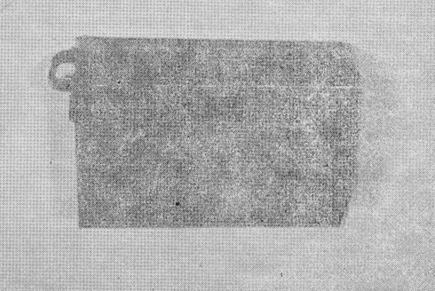
Cockpit
Voice Recorder
There
was a 10 mm puncture in one flat side of the orange dust-cover, some buckling
of' the dust-cover and a thin layer of light-brown mud adhering to the front
panel. There was no Sign of live damages.
The
dust-cover was removed by unlocking the rear fastener and sliding the cover off
the housing assembly. Some coaxing with levers was required to effect this step
due to general buckling.
The
armoured (tape housing) thermal box cover-lid showed a cut, into the soft outer
layer, which match the puncture in the dust-cover. This cut did not penetrate to
the metal ,core of the thermal box.
The
thermal box lid was removed and the magazine, contained inside, appeared to be
in good condition. The ablative material surrounding the magazine and lining the
thermal box appeared to be intact.
The
magazine (United Control, Data Division Part Number 103630 Serial Number 2218)
was then removed from the thermal box, the external bulk-erase coil removed and
the magazine carried from the Air Safety Investigation Branch Engineering
Laboratory to the ASIB Audio Laboratory.
Here
the outer covers of the magazine and the electrical connections to the erase
head were removed. The magazine and tape appeared to be in a very clean
condition and no foreign material was evident. However, as a precaution the tape
path over the record heads was cleaned with Isopropyl Alcohol. The cleaning
materials showed a very slight deposit of contaminants had been removed in this
cleaning process.
The
magazine was then mounted on a tape transport (United Control, Data Division,
Part number 101077-3 Serial Number 1001) and the four tracks of the recording
(i.e. area microphone, captain's jackbox, co-pilot jackbox, flight engineer
jackbox) played back through four separate and independent preamplifiers (Omega
Electronics Model EQ-25) onto four separate and independent tracks of a tape
recorder (Sansui Electric Co., Model QD-5500 S Serial Number 243070017).
By
this arrangement all members of the Sri Lankan investigation team were able to
hear the cockpit voice recorder played back through four speakers while the
four-track copy recording was being made.
Signal
to noise ratio on all channels was (subjectively) evaluated as good but there
was some distortion, suggesting over-modulation, on all channels and heavy
distortion of a similar nature on the area-microphone channel. Most of the
flight-deck conversation was in the Icelandic language and consequently
required
translation. Two cassettes copies, of the final 10 minutes from the
area-microphone channel, were then made for the use of the investigation team in
compiling a transcript.
A
further copy was made on a sound spectrograph (Voice Print Series 700) which has
a loop facility providing ready reiteration of any 2J second Period on the copy
tape. This facility was used by the investigation team to assist them in the
transcription process.
At
a later stage (14 December) two further cassettes (four tracks) were recorded so
as to provide the team with recordings of the four complete voice-recorder
channels, each 30 minutes in duration.
On
Friday 15 December I handed Mr. Rosa the 4 track (Sansui) copy tape, the voice
recorder magazine and 21 copy of the area microphone transcript which had been
compiled by the Icelandic-speaking members of the team with stenographic, typing
and Photocopying assistance from the Air Safety Investigation Branch.
The
Cockpit Voice Recorder chassis (less magazine) is being returned to the
Department of Civil Aviation, Sri Lanka via the Sri Lanka High Commission in
Canberra.
J.
C. HOPKINS,
for
Assistant secretary.
(Air
Safety Investigation)
AREA
MICROPHONE CHANNEL FROM TRANSCRIPT COCKPIT VOICE
RECORDER
REMOVED FROM DOUGLAS DC-8-63 REGISTRATION TF-FLA
Legend
Captain
- Captain of TF-FLA
CO-Pilot
- Co-Pilot of TF-FLA
FE
- Flight Engineer of TF-FLA
Chief
Pilot
- Icelandic Airlines
Radar
- Colombo (Surveillance) Radar Operator
//
//
- Explanatory or Editorial Note
(?)
- Unidentified Source
-
- -
- Unintelligible Word/s
(
)
- Words open to other interpretations
Time
From
Text
Min:Sec
10:09
CO-PILOT
It is twenty miles out
CAPTAIN Yes
CAPTAIN
Get me the message
9:52
CAPTAIN
Did you get the message there-on
//Stabilizer trim sound//
CO-PILOT Shouldn't we get it
from them
(?)
He was going to get it from them
9:33
CAPTAIN
Get it from them
9:08
RADAR
//Madras weather//QNH one zero one four
842
CO-PILOT
Yea just about one thousand feet till we reach our altitude
CAPTAIN Yes
(?)
Is the light on
No no
Wait awhile
Do you think the light is on
Yes
8:24
//Stabilizer trim sound//
CAPTAIN Yes
CO-PILOT Lets see AAA the
distance is one hundred AAA three
CAPTAIN Hand this to me
(?)
Two thousand and five
7:34
CO-PILOT
It is AAA what from AAA India Sierra
7:21
CO-PILOT
It is checked//stabilizer trim sound//bravo India Sierra
CO-PILOT Need one - -
//Stabilizer trim sound//
6:49
RADAR
You are fifteen miles from bravo delta kilo
(?)
Altimeter
Co-PTLOT We are going over
CAPTAIN Yes Yes
6:42
Co-PILOT
One can see down
CAPTAIN Yes
CAPTAIN OK lets have
twelve degrees of flaps
6:34
CO-PILOT
They are coming twelve
CAPTAIN The flaps
eighteen
CO-PILOT The flaps ten asked
for twelve
Co-PILOT The flaps are
eighteen on her
(?)
Thats right
CAPTAIN Flaps twenty
three
6:11
Co-PU.A)T
They are twenty three and light is out
5:32
RADAR
Lima Lima Zero Zero One
5:29
CAPTAIN
Repeat this
CO-PU,OT One zero one four going
through four
CAPTAIN Yes
FE
ADF
CAPTAIN It is ADF here
5:19
CO-PILOT
Hey then I will just put up the ILS on my side
CAPTAIN Hey, namely
heading, you see, for seventy eight this last there is a bit
CO-PILOT This must be a
miscalculation from them
5:09
FE
Galley power is on and fuel panel set
(?)
Then we are down to before landing
(?)
Yes
4:59
CAPTAIN
Can you turn down the lights there as much as possible
CO-PILOT Yes
(?)
Can you check the circuit breakers for the passenger lights if they -
have
had
them in
(?)
It is all set
(?)
All in yes
4:11
RADAR
One four track miles to run range twelve miles North North East of
Bravo
Delta Kilo
Co-PILOT Yes-almost one
thousand for our altitude
3:15
Co-PILOT
Do you want the lights
CAPTAIN Yes put them on
Co-PILOT Do you want the
lights on or AAAMMM
CAPTAIN Put them out, just
put them out//meaning leave them in down position//
Co-PILOT
Yes
3:01
CO-PILOT
Well we are nine hundred to the altitude
CAPTAIN Yes
2:40
RADAR
Lima Lima Zero Zero one turn right heading Two Two Zero
FE
- - - - - - -
(?)
There is quite a lot of precipitation in this
(?)
Yes
2:16
CAPTAIN
Final check list
(?)
They are on and armed
(?)
- - - - - - -
(?)
- - - - - - - up through this - - - - - approaching this
CAPTAIN Just take the
radar off now
CO-PILOT Off
(?)
Yes
(?)
There is some weather in this
CAPTAIN Yes Yes
(?)
There is - - - - - - light here
CO-PILOT We are visual
(?)
Runway in sight
1:40
(?)
Runway in sight
FE
Reverse hydraulic pump
CO-PILOT Yes light is on
FE
No smoking
(?)
Yes
CO-PILOT
Two thousand feet and the flaps are thirty five
1:37
CAPTAIN
Flaps full
CO-PMOT Full flaps
FE
No smoking
Co-PILOT No smoking
coming on
FE
Ignition overide
(?)
Coming overide here
1:23
FE
And radar altimeter
CO-PILOT It is set at two
thousand feet
(?)
Well well
1:18
CAPTAIN
Put it on two fifty now
CO-PILOT It is set to that
here
FE
Spoilers
(?)
What did you say
1:08
FE
Spoilers
1:06
CO-PILOT
They are armed
FE
Anti skid
CO-PILOT
It is armed
FE
Altimeters
:59
CO-PILOT Yes we have one thousand
one four
:54
RADAR
Height should be one thousand feet
FE
Landing flaps
CO-PILOT
They are down
CO-PILOT
Do you want the landing lights
:30
FE
Then we have flag scan
(?)
No flag
:21
CO-PILOT Runway in sight
CAPTAIN The lights on
now
CO-PILOT The lights are coming
on
:14
//Sound of rain starts here//
(?)
There is lightning
:12
CAPTAIN
Anti skid is on her
FE
HA//questioning tone of voice//
:08
CAPTAIN
Lets have the windshield wipers on
CO-PILOT
Yes
:05
CO-PILOT You are in the red on the
VASI lights
:03
CAPTAIN
Max - Power - Climb
00:00
//Sounds of impact begin//
:05
//End of recording//
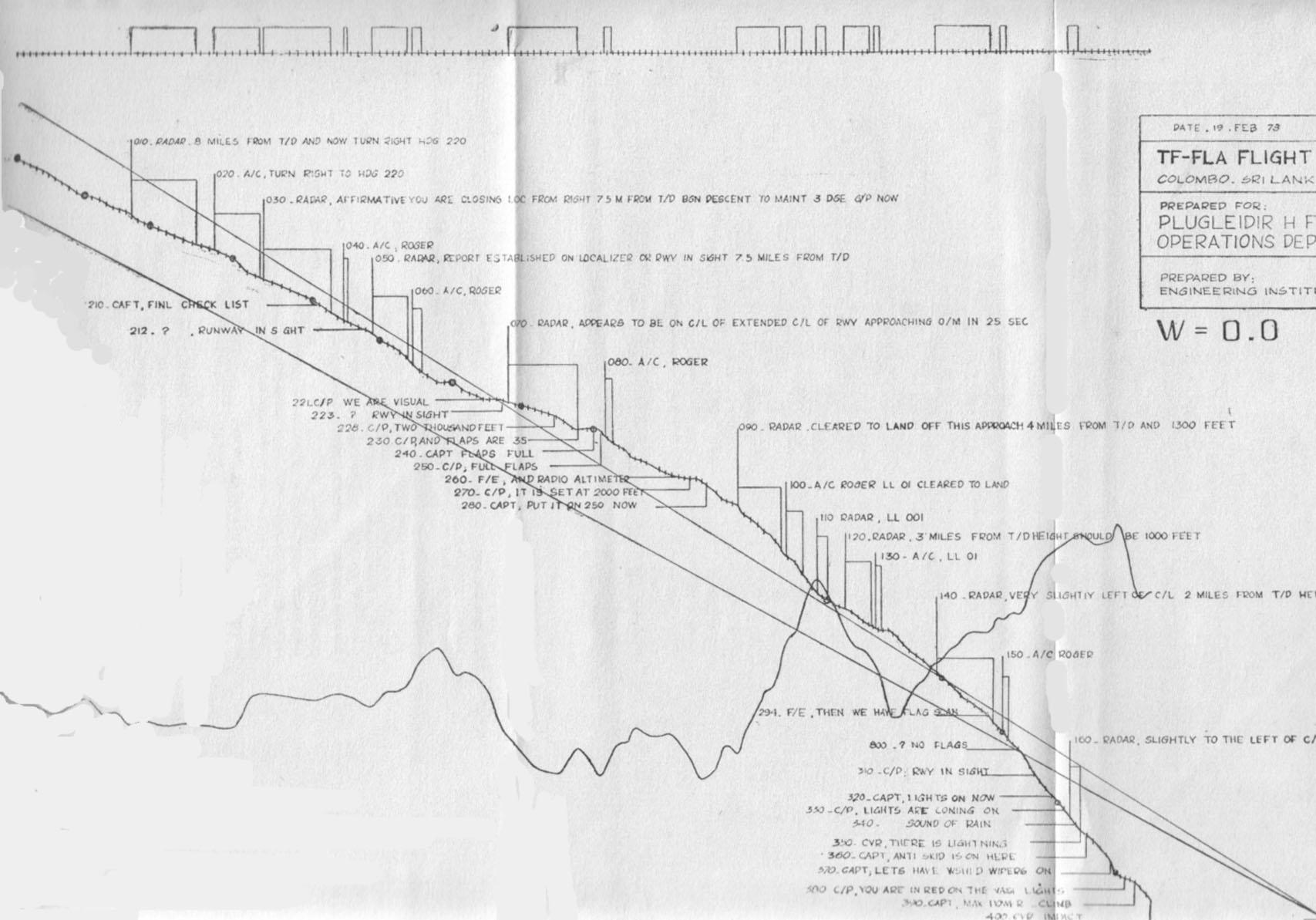
Flight
Data Analysis
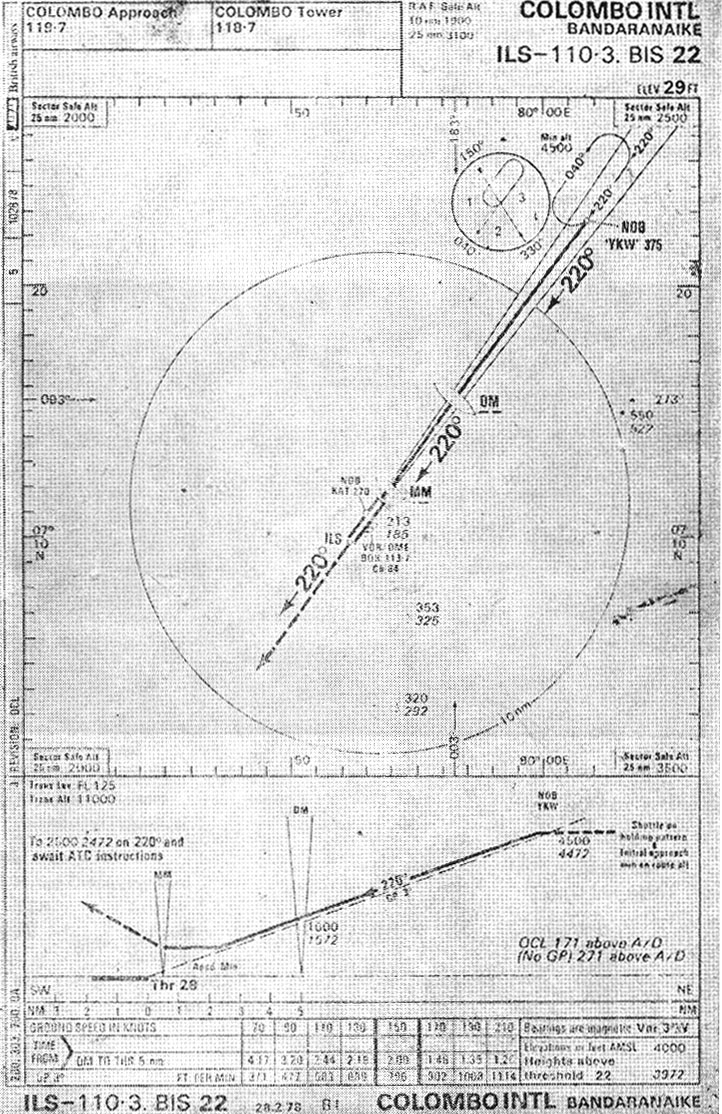
Colombo
Approach Diagram
RADIO
ENGINEERING DIVISION, BIA
Daily Meter Readings-Instrument Landing System
|
|
Localizer |
|
|
|
|
|
Course/Clearance Equipment |
|||
|
|
No.1 |
|
No. 2 |
|
|
Transmitter |
Course |
Clearance |
Course |
Clearance |
|
Oscillator |
4.4 |
5.1 |
4.5 |
5 |
|
Ist
Doubler |
7 |
6.2 |
70 |
60 |
|
2nd
Doubler |
8.2 |
9 |
8 |
5.5 |
|
I
st RF Amp. |
4 |
3.5 |
3 |
4.5 |
|
2nd
RF Amp. |
14 |
14 |
14 |
13 |
|
Driver |
16.1 |
17 |
17 |
16.5 |
|
Power
Amp. |
8 |
8.5 |
7 |
8 |
|
RF
Output |
4.5 |
12.5 |
10 |
10.5 |
|
Power
Supply |
14.2 |
13 |
13 |
12.5 |
|
Monitor |
|
|
|
|
|
Off
Course Sens. |
Lo |
Lo |
Lo |
Lo |
|
Off
Course Meter DDM |
0/+ |
6 |
-1 |
+04 |
|
Off
Course DDM Indicator |
165/150 |
158/150 |
160/150 |
160/150 |
|
On
Course Sens. |
Lo |
Lo |
Lo |
Lo |
|
On
Course DDM Meter |
1 |
18/150 |
-4 |
-4 |
|
On
Course DDM Indicator |
025/90 |
90 |
24/90 |
17/150 |
|
Pos.
Volts |
85 |
87 |
90 |
85 |
|
Off
Course Path Level |
95 |
100 |
105 |
105 |
|
On
Course Path Level |
100 |
100 |
90 |
110 |
|
Meg.
Volts. |
105 |
100 |
100 |
105 |
|
RF
Level |
110 |
105 |
105 |
110 |
|
Modulator : |
|
|
|
|
|
Sideband
Phaser |
52 |
30 |
40 |
16 |
|
Sideband
Amplitude |
41 |
20 |
50 |
37 |
|
Modulation
Balance |
20 |
21 |
27 |
26 |
|
Modulation
Percentage |
24 |
0.91 |
13 |
14 |
|
|
|
|
|
|
|
Ant. Changeover: |
|
|
|
|
|
Power
Output |
Forward |
|
|
|
|
CSB |
Reverse |
|
|
|
|
SB |
Forward |
|
|
|
|
|
Reverse |
|
|
|
|
A/C
Voltage |
Unregulated |
|
|
|
|
|
Regulated |
|
|
|
|
|
|
|
|
|
|
Aircond. |
Telephone |
Tools |
|
|
|
|
|
|
|
|
|
Date 3.11.7 8 |
Signature |
|
|
|
LIST
OF SPECIFIC ABNORMALITIES RECORDED IN THE
KATUNAYAKE
ATC LOG BOOKS
|
Abnormality |
Day/month/time |
|
|
|
|
|
|
Glide
Path unreliable to |
21/l/1245,24/3/ |
|
|
|
|
|
|
Glide
Path useless |
20/11/0239 |
|
|
|
|
|
|
Glide
Path unusable |
16/11/1332 |
|
|
|
|
|
|
Glide
Slope unserviceable |
28/10/0045,
28/10/0545, 28/10/1128, 29/10/0810, |
|
||||
|
|
30/10/0600,
31/1010500, 3/11/0335, 3/11/0700, |
|
||||
|
|
4/11/0832/1611,
51111 1545, 6/11/0755/0800 |
|
||||
|
ILS
faulty |
2/12/2210 |
|
|
|
|
|
|
ILS
power loss |
26/10/1318,4/11/1821/2200,5/11/0752
on 30 occasions/1440, |
|||||
|
|
10/11/1730,
13/11/2300/2355, 29/11/0043, 22/2/0800 (alarm) |
|||||
|
|
16/11/1540, |
|
|
|
|
|
|
ILS
unserviceable |
22/10/1035,
26/10/0929, 28/10/1900, 29/10/1900, 30/10/ |
|||||
|
|
0600/0815,
4/11/1850, 5/11/0830, 10/11/0145/0600/0627, |
|||||
|
|
11/11/0810,
13/11/2300, 14/1030, 20/11/1615, 3/12/0130, |
|||||
|
|
14/11/0605/0800 |
|
|
|
|
|
|
ILS
tripping |
22/10/2300,
26/10/1930/2345, 31/10/0220, 1011111605, 12/11/ |
|||||
|
|
0010
frequent /1609 now and then. 13/11/2106,14/11/2010/ |
|||||
|
|
2330,
15/1110200/2310/2326 (crash) 16/11/1656 very |
|
||||
|
|
minute
17/11/0031/0033/0829/1130/1310/1444, 22/11/many |
|||||
|
|
times,
14/12/1758/1915 every often 25/12/1400 |
|
||||
|
IIS
off the air to |
19/10/0545 |
|
|
|
|
|
|
ILS
misleading |
28/10/0545 |
|
|
|
|
|
|
Up
and Down |
14/2/0810,19/2/0015 |
|
|
|
|
|
|
Status
not known |
28/10/0054,
3/11/1607, 4/11/0635, 7/11/0800/110(), 16/111 |
|||||
|
|
1340/1600,11/11/1040 |
|
|
|
||
|
Misleading |
28/10/0054,
28/10/0545 |
|
|
|
||
|
Never
picked up |
28/10/0054,
31/10/0220, 16/11/1126, 3/11/0400. |
|
||||
|
Tripping |
1/12/1751
four times /1752, 5/12 (all the time) 7.9.9.10.11- |
|||||
|
|
frequent
trippings, 13/12/1242-1244 9 times. 15/12/1823- |
|||||
|
|
12
times. 24/12/1852, 25/12 continuously, 9/2/2010 |
|
||||
|
|
(too
often) |
|
|
|
|
|
|
Dip |
2/2/1510,14/2/0810 |
|
|
|
|
|
|
Erratic |
6/11/1430,10/2/1924 |
|
|
|
|
|
|
Low |
2/12(2010/2205 |
|
|
|
|
|
|
Fluctuating |
28/11/oscillates.
6/12/0050, 6/2/0850 |
|
|
|||
|
Unsteady
|
16/11/1332,
30/12/1430, 23/1/1150 (unstable) 19/2/0015. |
|||||
|
|
|
|
|
|
|
|
|
Fly
low |
28/12/1140,
12/1-79/0730/2100, 10/2/1842, 12/2/0830 |
|
||||
|
Fly
down |
12/1/2100,
12/111245, 10/2/0810,14/2/0810 |
|
|
|||
|
Abrupt
change |
6/2/0850,
12/2/ 0830 |
|
|
|
|
|
|
2½-3
dots fly down |
10/2/0810 |
|
|
|
|
|
|
Outer
marker u/S |
19/10/0600,
26/10/2345, 29/10/0810, 12/11/0010, |
|
||||
|
|
16/11/1120t
1540 |
|
|
|
|
|
|
Localizer
u/s |
4/11/0635/0950/1611,
14/2/0810 |
|
|
|
||
|
'Did
not pick up VASIS |
12/11/25 |
|
|
|
|
|
|
VASIS
u/s |
13/11/2106 |
|
|
|
|
|
|
Negative
indication |
23/10/1607,
16/11/0800, 13/11/1600 |
|
|
|||
|
Markets
never picked up |
28/11/
2/12/2010, 6/12/0050 off set localizer 2/12/1010, |
|||||
|
|
2/2/1510,
19/2/0015, 2/12/2205, ILS on test 3/2/0800 |
|
||||
Note.-The recording of -the above abnormalities was prompted by one or
more of the followings
(a)
Reports from pilots or other flight crew members
(b)
Reports from radio technical staff
(c)
Observations of the air traffic controllers.
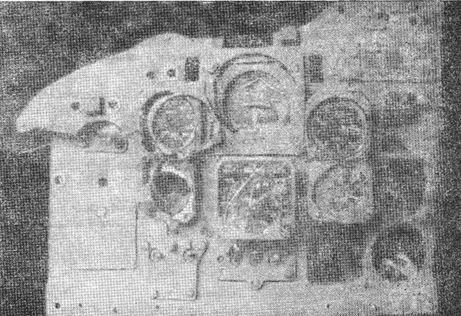
Instrument
Panel recovered from the wreckage
